PiProjector 1.x series documentation
Bought a PiProjector Rev 1.x from my Tindie store? Here’s all the documentation to get you up and running.
What does the PiProjector do?
The DLP2000 is a relatively cheap DMD, (Digital Mirror Device). It supports a resolution of 854 x 480. Not huge, but TI are selling their “evaluation boards”, (the DLP2000EVM), for around US$99 which is pretty cheap for a projector. However, these evaluation boards are only designed for the BeagleBone.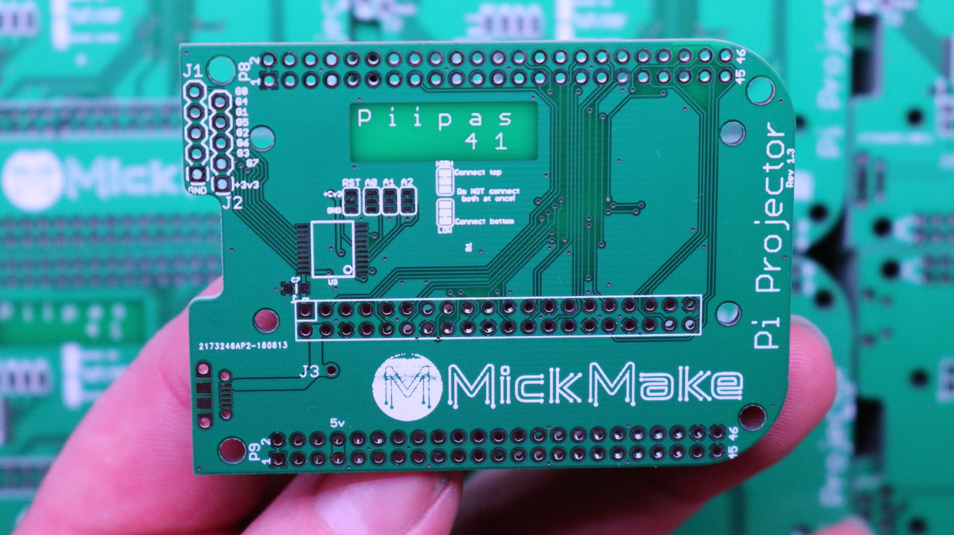
So this is a simple adapter board that allows you to use an ordinary Raspberry Pi Zero W instead of a BeagleBone. The Raspberry Pi is one of the few SBCs around that have a working 8bit RGB LCD interface. The other one is the TinkerBoard.
So, since the DLP2000 was too cool to pass up, I wanted it to work on a Raspberry Pi Zero W and see if I could actually make it the cheapest, smallest pocket projector around.
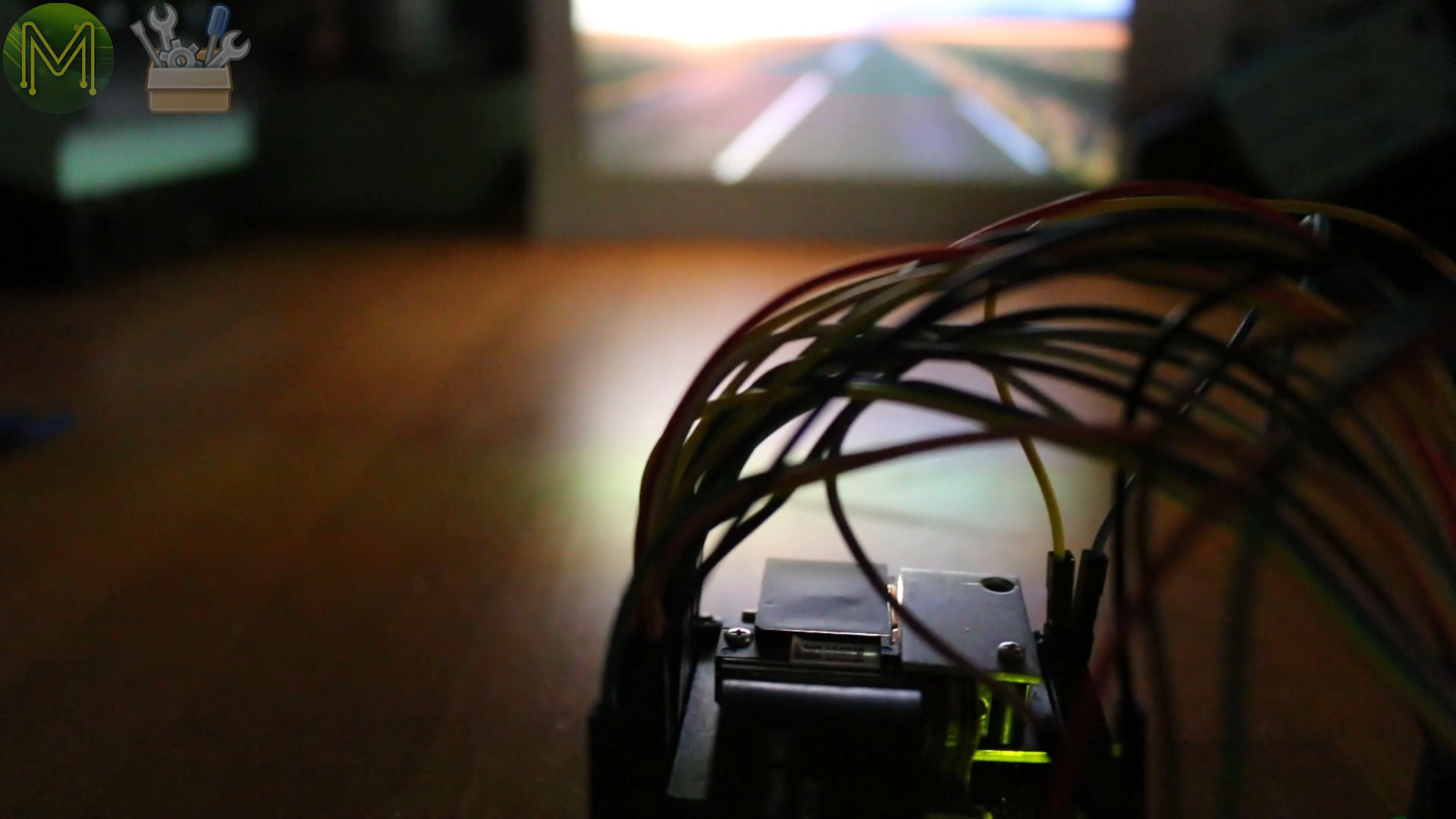
This adapter board makes it a much cleaner, more permanent install for a Pi Zero W rather than a rats nest of wires. (If you saw my video on this, you would understand.)
If you’re looking for the same PCB, but with LiPo battery charging support, then check out the Rev 2.x series of this board on Tindie. Gives you 1h of continuous video playback per Ah of battery.
Buying it on Tindie
The Rev 1.x series I’m selling as a plain “as is” PCB without the SMD I2C expander and headers soldered on. I do sell the headers on my Tindie store, but not the I2C expander yet.So, you will also need:
- A DLP2000EVM module.
- Two 2x23 pin female headers - or add it to your Tindie order here.
- One Pi male header - or add it to your Tindie order here.
- Short jumper cable to connect 5v power to DLP200EVM.
Who’s using it?
Here’s a small list of how people are using my PiProjector. If you buy one, drop me a note on how you’re using it and I’ll post it here.
- International Space Station (ISS) - Exposing colour patterns on WORF plates.
- Dentists & Orthodontists - Instead of hanging a heavy screen above a patient’s head.
Who’s talking about it?
A bunch of people seem to be interested in this little project of mine for some reason:
Mounting options
So you have your brand new PiProjector PCB. What now? Here’s a couple of mounting options for you.
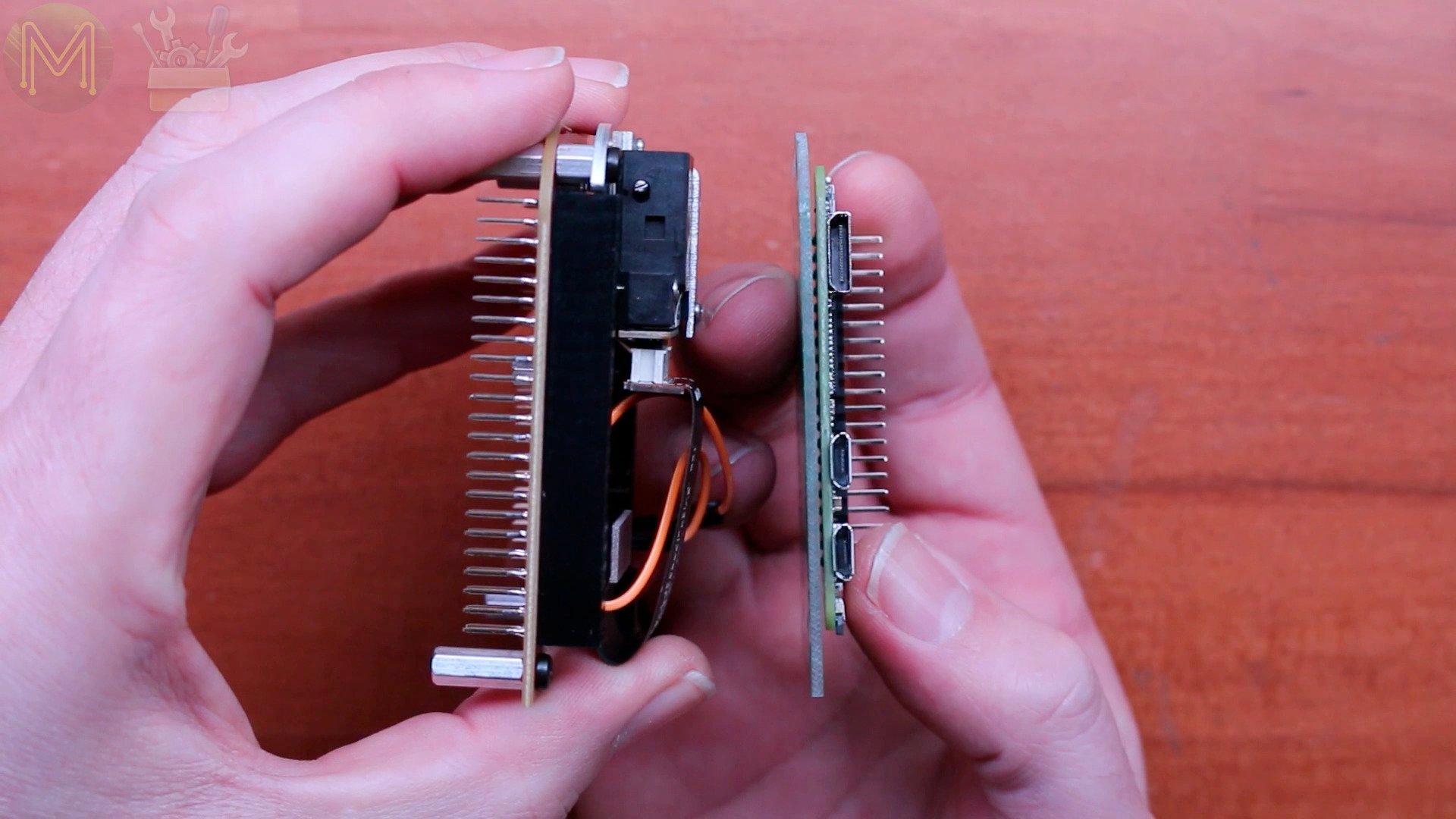
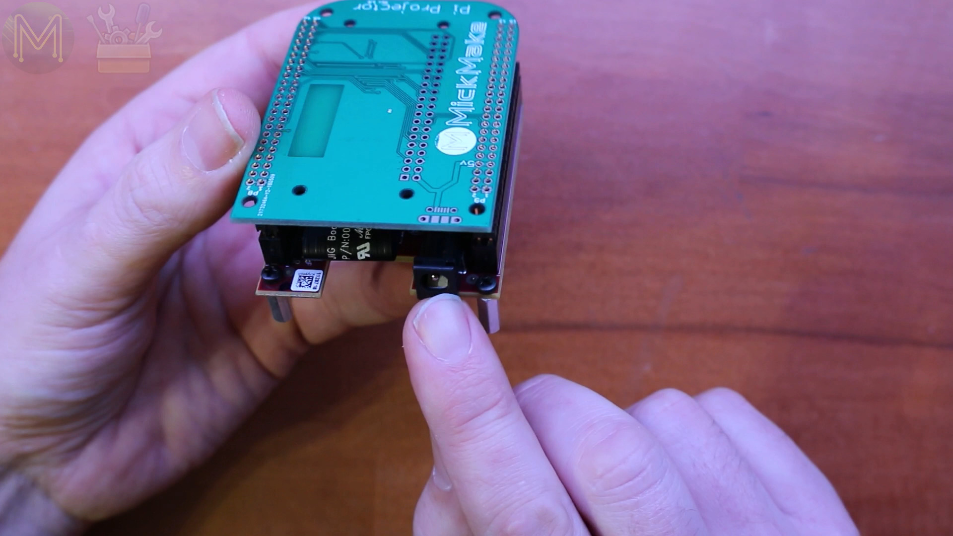
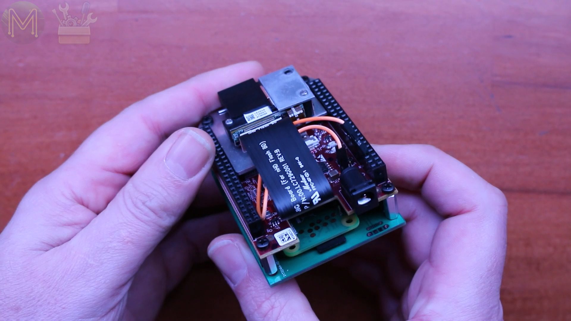
The Pi Zero W is mounted onto the PCB by directly soldering or by header.I’ve added two large ground planes to make the display output rock solid, but also provided a void so that the WiFi signal isn’t attenuated.The Pi Zero W can be mounted either underneath the PCB, or on topand the PCB can be mounted either on top of the projector, or underneath.Whichever way you mount it, just make sure the micro-USB power connector is lined up with the DC jack on the projector.The smallest footprint will be this configuration. However, note that you will only have access to the Pi Zero W over WiFi. You won’t be able to get access to the USB connectors.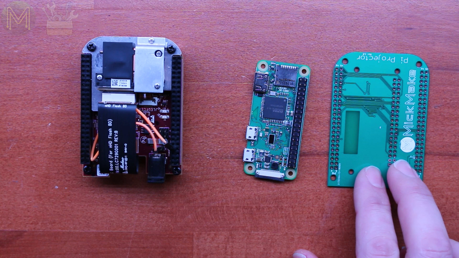


Also, it is possible to use a Pi2 or a Pi3, but this board has been optimized for a Pi Zero W. Check below for further mounting options.
Soldering up
When mounting the board this way, you’ll need two 2x23 female headers and one 2x20 male header. Solder these up to the PiProjector board.
Next grab your Pi and place it face down on the PCB. The plastic spacer on the header will provide enough space so the Pi will lie parallel to the PCB.
Then solder this up. To keep the board flat, you can solder one pin while holding the Pi and then let it cool down. Then solder up the rest.
Then before adding the DLP2000, there’s one more thing to do.
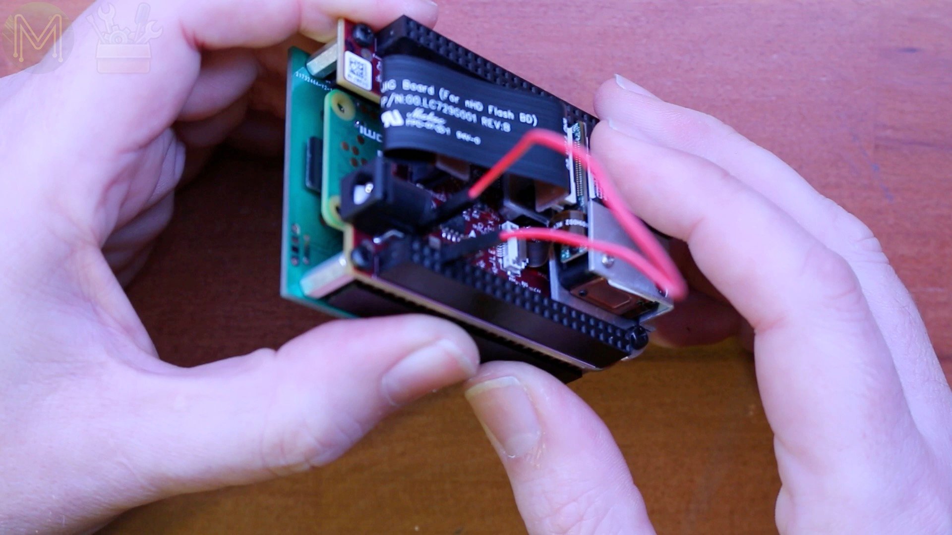
The TI guys didn’t bother to connect up the 5v power lines on their DLP2000EVM board and left it empty. There’s several ways of fixing this:
Solder up a jumper wire directly on the DLP2000.Add a jumper wire on top, which is a little untidy.Or you could de-solder the power header on the DLP2000 and make use of the handy via I’ve added. This lines up perfectly with the power pin on the DLP2000.You will be able to add a female header to the underside of the DLP2000 and a male header on the PiProjector PCB.

Making changes to your Pi
Then apply power to the Pi, which will also power the DLP2000. I’m assuming you have a running Pi already with the latest Raspbian or Armbian image. If you don’t, then check out my Pi setup videos.
Once booted, login to your Pi and you’ll need to edit two files.
The first is the /boot/config.txt file. Add the following to the end.
# Added to support DLP2000
dtoverlay=i2c-gpio,i2c_gpio_sda=23,i2c_gpio_scl=24,i2c_gpio_delay_us=2

dtoverlay=dpi18
overscan_left=0
overscan_right=0
overscan_top=0
overscan_bottom=0
framebuffer_width=854
framebuffer_height=480
enable_dpi_lcd=1
display_default_lcd=1
dpi_group=2
dpi_mode=87

dpi_output_format=458773
hdmi_timings=854 0 14 4 12 480 0 2 3 9 0 0 0 60 0 32000000 3
What this does, is to change the I2C interface to other pins so that they don’t clash with the LCD GPIOs, which are configured using the DPI18 Device Tree overlay. The rest of the lines are options specific to this particular display.
Next download the PiProjectorControl.sh script from GitHub, and place it in /usr/local/bin. Don’t forget to make it executable.
chmod a+x /usr/local/bin/PiProjectorControl.sh
Next you need to edit /etc/rc.local and add these lines.
/usr/local/bin/PiProjectorControl.sh setup
/usr/local/bin/PiProjectorControl.sh on
This will configure the DLP2000 to use the Raspberry Pi GPIO lines for the display instead of the default splash screen and turn the display on.
If you haven’t already enabled I2C on your Pi, you can run raspi-config to do this.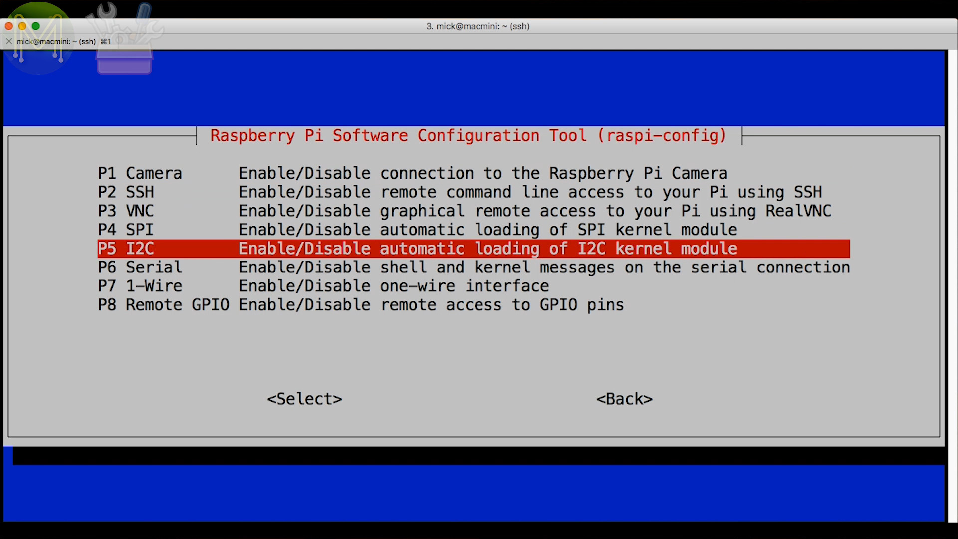
Powering it up
Next add power. You can use either the DC jack or microUSB port for this.
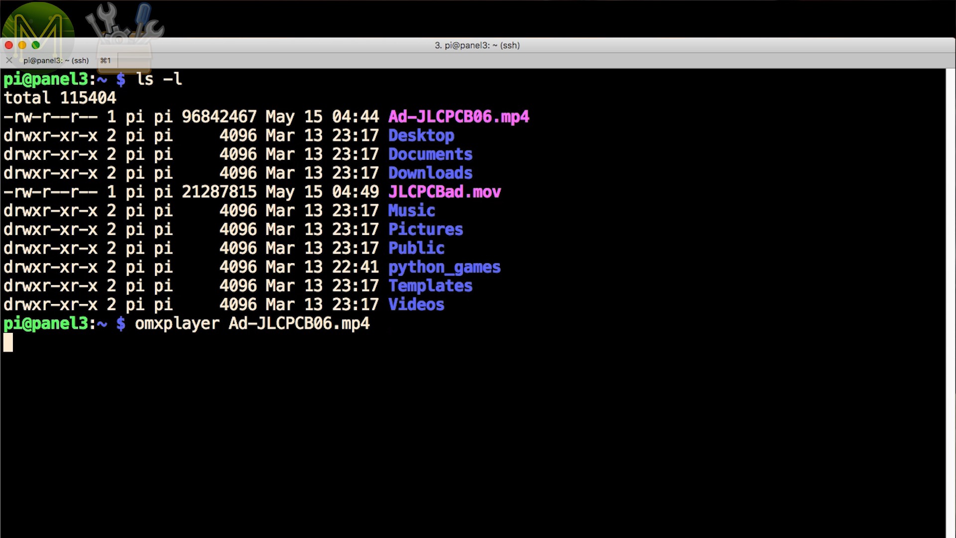
And there you have it! A decent little portable display. Visible even under my studio lights, but better in a darkened room.If you want to play a video, then you can use the Pi’s optimized video player for this and for sound you can use a Bluetooth receiver.
Power requirements
OK. So what sort of power pack should you use to power this thing?
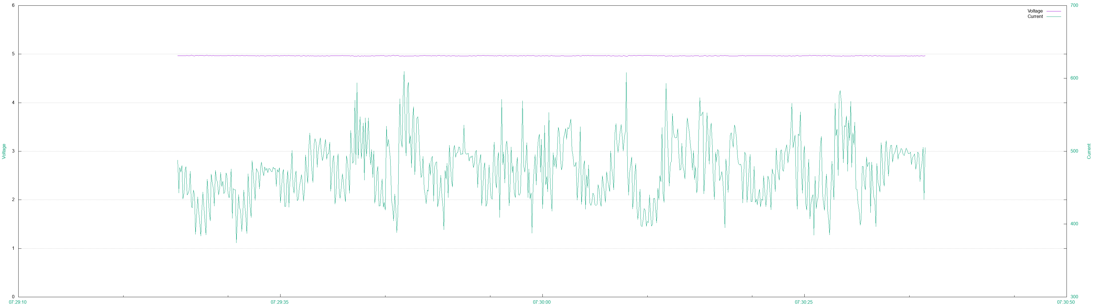
I attached it to my desk power supply with an inline power monitor to see what current draw there was.
When booting up and sitting idle it drew a max of 673mA with an average of 373mA. Pretty decent, considering the specs both TI and Raspberry Pi suggest for their power packs.
On the other hand, while playing a video there was a max of 609mA with an average of around 470mA.
Need a case?
I’m starting to see people making cases for the PiProjector.
One of them is up on ThingiVerse. Check it out!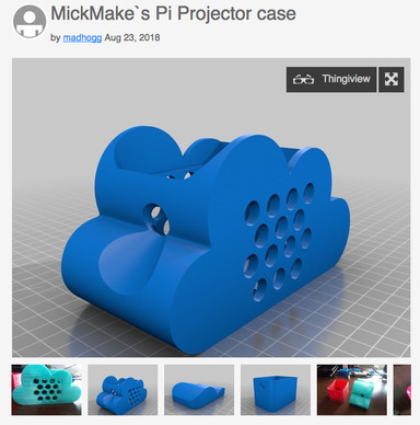
Let me know of any others, and I’ll add them in here.
Board Revisions
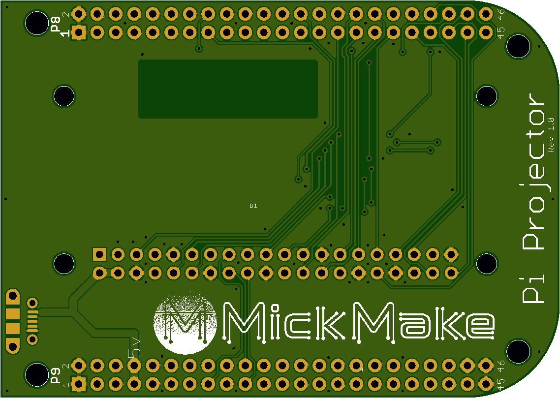
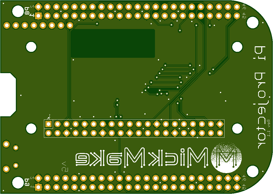
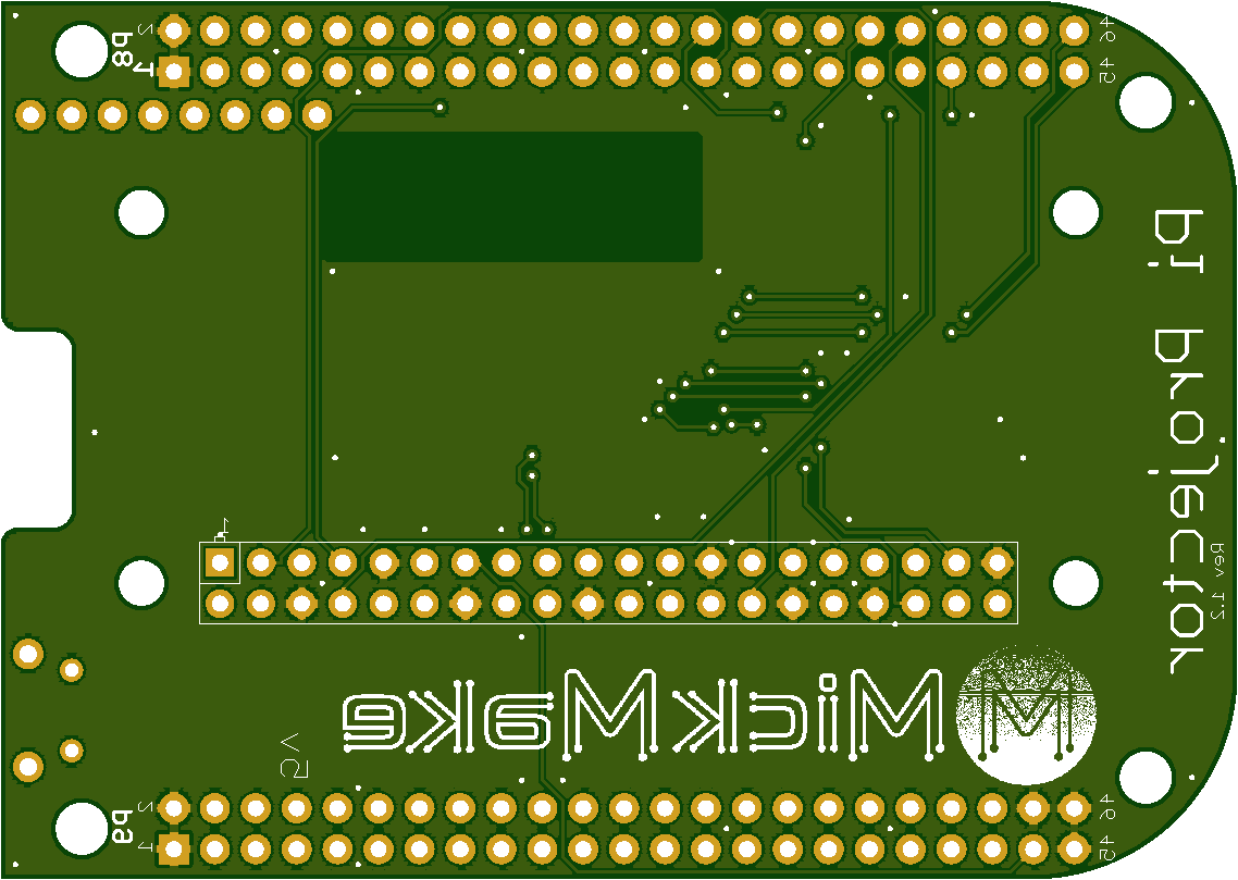
This PCB is a straight header to header adapter board. With the ability to power from a micro USB connector or from the DC jack on the DLP2000EVM. A nice big ground plane gives a rock solid display, but I’ve left a void so that it doesn’t interfere with the Pi Zero W WiFi signal.
You can also mount the Pi Zero W above or below the PCB and mount the PCB above or below the projector, depending on how small you want the unit to be.
Note: I’m only selling the most recent version on my Tindie store.
PiProjector Rev 1.0

The original basic version. Just a plain PCB so you don’t have to do all the wiring up.
PiProjector Rev 1.1
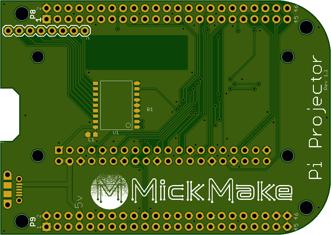
I added a place for an MCP23008SO SMD, which is an 8 port GPIO I2C expander. This solves the issue of all the GPIOs being used up by the projector. I won’t be shipping this as part of orders, so you’ll have to solder one up yourself. Note: the board still works without it being present. I also added a cut-out on the PCB to allow adding/removing the Pi Zero W SD card easier.
PiProjector Rev 1.2

Small change to the cut-out to allow easier insertion of the SD card and some minor track changes.
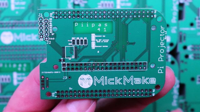
PiProjector Rev 1.3


- Moved GPIO headers to the edge of the board.
- Added DLP power pin, so you don’t need a jumper cable.
- Added I2C GPIO expander solder tabs to change I2C address.
- Minor track changes.
Also check out Rev 2.0 of the board.
DLP2000 Specs
- Max resolution: 854 x 480.
- Focus range: 10" to 60" - although I’ve managed to project down to 1" all the way up to 230".
- Lumens: 30 - Visible under most lighting, but better with a darkened room.
- Heat: It does get toasty, but not hot. Up to 40C, (104F), with an ambient temperature of 20C, (68F).
Note 1: There’s no keystone, so the projector has to be parallel to whatever you are displaying it on.
Note 2: The focus adjustment of the DLP2000EVM is a little “flaky”. I’ll be adding in servo controlled adjustment in a later revision.
Linky links
- YouTube video on the PiProjector
- Original video website article
- The PiProjector on the MickMake Tindie store.
- Schematics and other docs on GitHub.
Alternative mounting
If you really do want to mount the PCB on top of the projector with the Pi Zero W underneath the PCB, make sure to get extra long male header pins. The ones I had on hand were just a little short for this unfortunately.
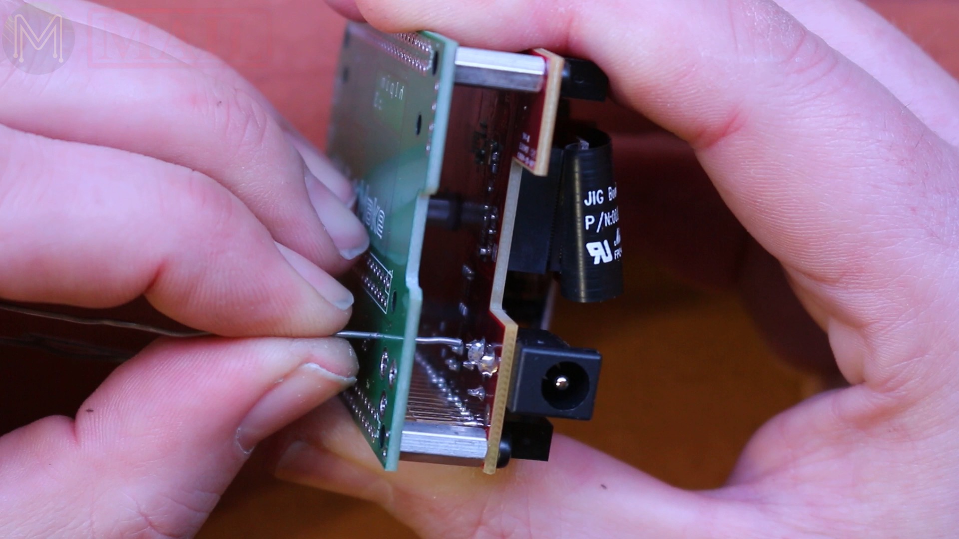
If you can’t find any, then you could always treat the Raspberry Pi as a module and directly solder. This method requires a bit of skill, but it’s workable.First, add some insulation tape to the bottom of the PCB. It’s not really required, but more of a “just in case”.Then line up the pins as best you can. You can use a header temporarily for this. Then solder the first point down. It’s important to make sure that both PCBs are as close as possible to each other. Any gap and you won’t have a proper solder joint.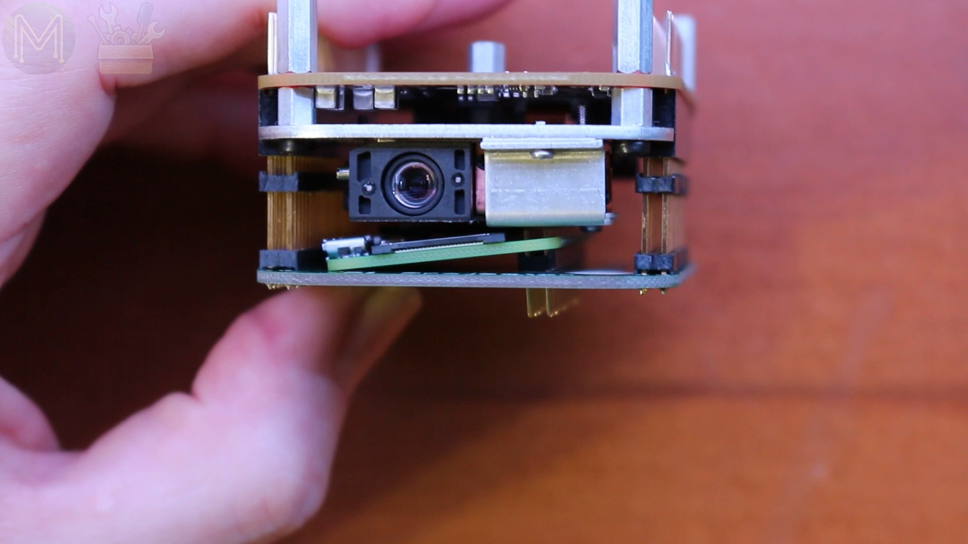


Then go along and solder the rest of the vias. Turn it over and solder on the other side to make sure there’s a solid solder joint.
It’s not really a recommended way of doing it, but just another option.
Doing it yourself - the hard way
I priced my adaptor board on Tindie fairly reasonably, but if you want to resort to a big ol' mess of wires. Then you can wire it up yourself.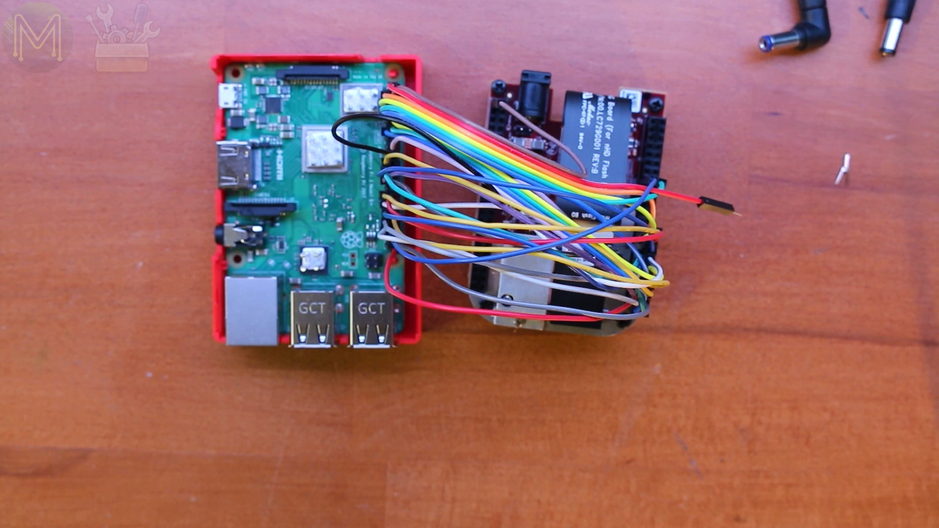
It’s not too hard.
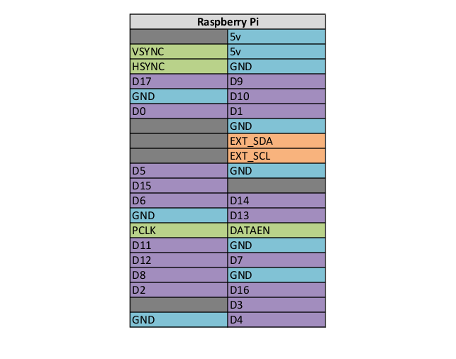
This is the GPIO layout on the DLP2000.And for the Raspberry Pi side.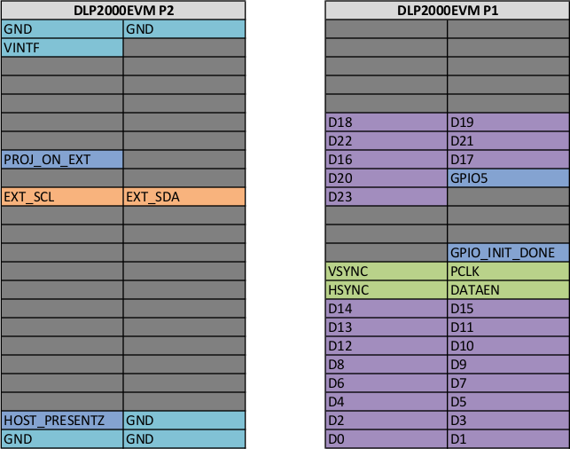
Once you have it all wired up, make the changes as noted above, then reboot the Pi and you’re done! Easy!
Except for the big ol' mess of wires…
So, that’s about it. Don’t forget you can pick up this adaptor board from Tindie.