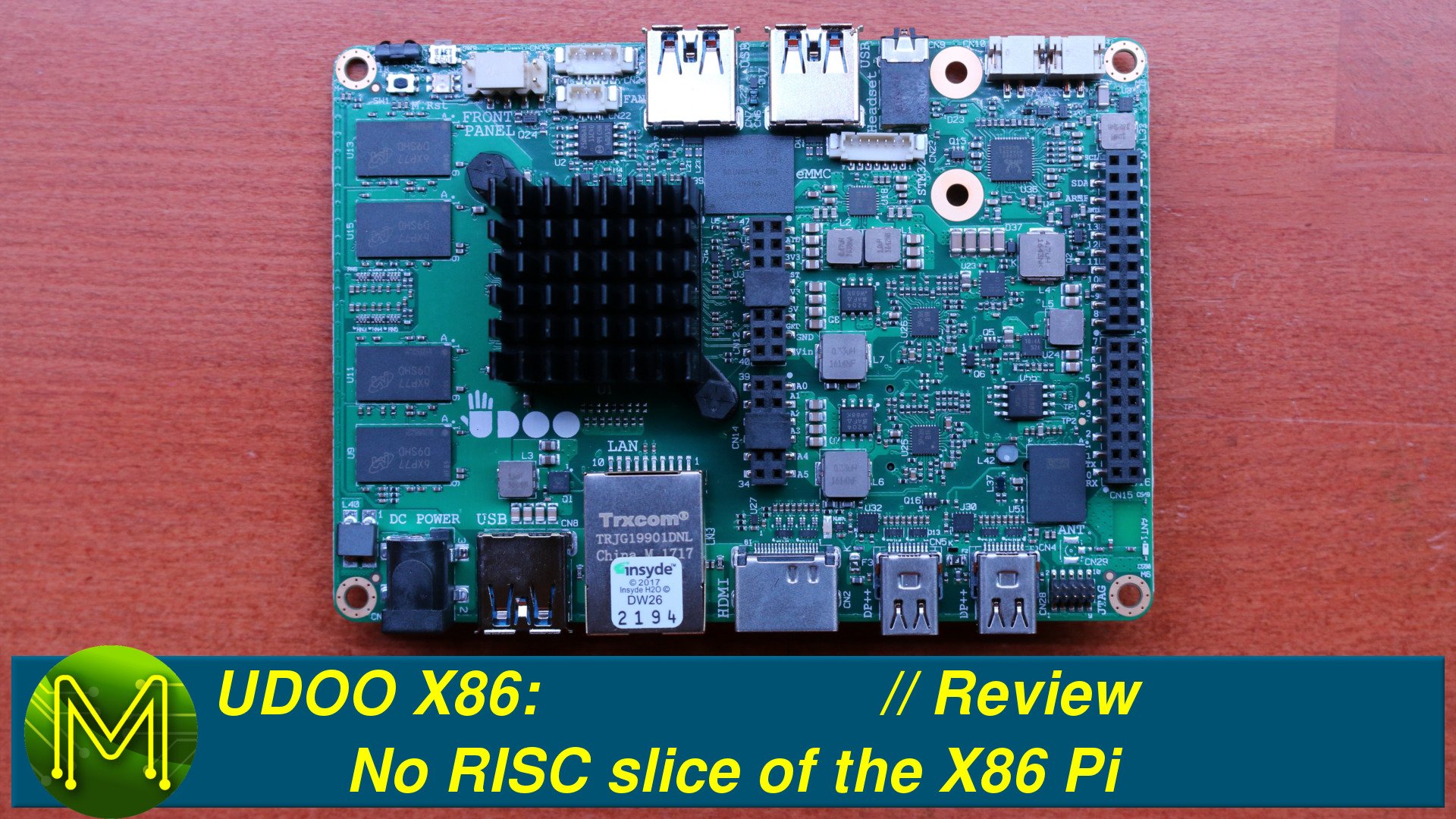
UDOO-X86: No RISC slice of the X86 Pi // Review
Another X86 based SBC hits the market. What’s this new board like? How good is it?
In Part 1 of the UDOO-X86 review, I take a look at how this board performs for the electronics Maker.
Unboxing
I originally thought that this board was a review board sent to me by UDOO, but due to a mix up on my part it was actually a pre-order I placed a couple months back.
The UDOO-X86 is packed with features and comes in 4 different variants. The Ultra, Advanced Plus, Advanced and Basic. The only things separating the four are the CPU, RAM size, and on-board eMMC. The price-point puts them fairly within the Pro-Maker, advanced Maker and small-business.
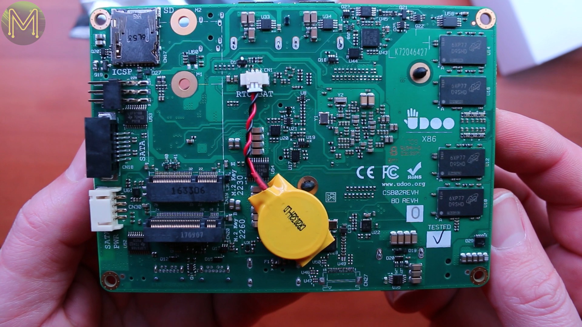
The Ultra is essentially a full fledged desktop PC. So, let’s find out what you get for your money.This board I have is the Advanced Plus. So, starting from the top right working clockwise: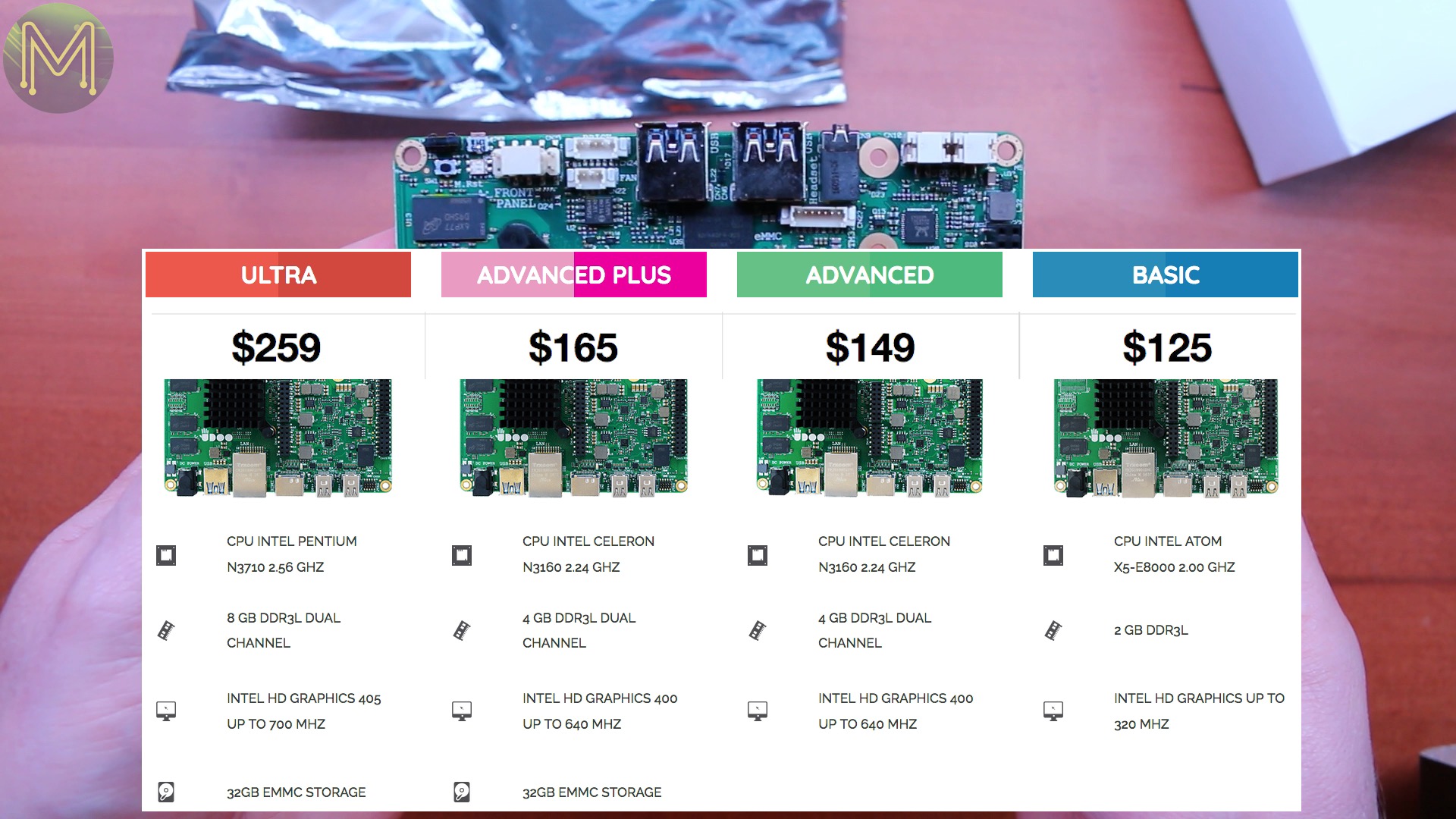
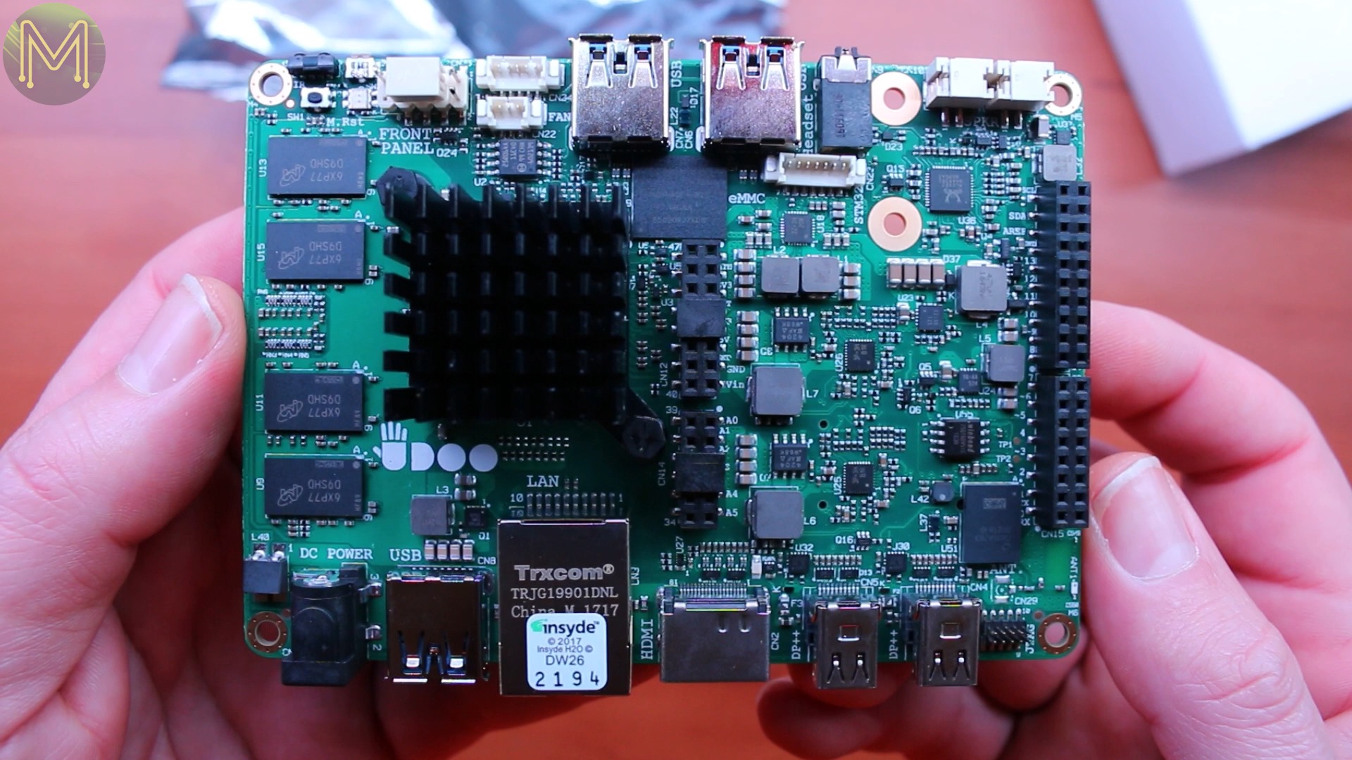
- Arduino compatible headers, coming from the Intel Curie below.
- A second line of GPIOs, from the Braswell Intel CPU and STM32, which is underneath.
- JTAG header.
- Two mini Display Ports,
- and HDMI all of which are 4K capable.
- GbE.
- USB3.0 port.
- DC power jack.
- Up to 8G DDR3 RAM.
- Infrared transceiver.
- Intel Curie reset button.
- Power button, and LED.
- PC style front panel connector, giving you reset and power buttons as well as system status.
- Brick connector.
- Fan power, which is PWM controlled by the on-board STM32.
- Two more USB3.0 ports.
- 32G eMMC on the Ultra and Advanced Plus.
- STM32 JTAG connector.
- TRRS audio jack.
- And unusually, amplified stereo speaker connectors.
- Both of which are connected to an ALC283, (U36), audio chip.
- An RT5041A, (U18), power chip that isn’t a PMIC, so you can’t control any voltages from the O/S.
- SPI flash - N25Q064A11E, (U2).
- Even more SPI flash - W25Q16DVSSIG, (U55).
- A handful of power control chips, (U23, U24, U25, U26).
- and Logic level converters - 74CBTLV3125BQ, (U30, U32). On the flip side there is:
- More Gigs of RAM.
- Interestingly, there’s also a MIPI-CSI connector, but my board didn’t have the connector soldered on.
- Two M.2 key slots for Wireless and SSD cards.
- SATA power, and SATA connector.
- And it seems they ran out of space for the Arduino SPI connector and so it’s placed underneath.
- Micro SD slot.
- RTC battery.
- SPI EEPROM - CAT25010YI, (U58).
- Speaker amplifiers - AP2142AMP, (U33,U34,U35).
- DDR RAM power control - RT8231AGQW, (U22).
- More logic level converters - LSF0108, (U52,U53,U54).
- Ethernet driver, (U28).
- STM32 - STM32F100R4H6B, (U43).
- and there’s no shortage of bus converters - PCA9517DP, (U45).
- 74LVC07ABQ, (U17,U20,U44). A lot of effort has been taken to ensure that this board has 5 volt tolerant GPIOs. So far I can’t fault the design.
In terms of physical size, it’s quite a bit bigger than the similar LattePanda, around the same size as the HiKey960 and twice the size of the humble Pi.
Such a beefy board requires a lot of juice. UDOO provides a 12v, 3A wall wart to use, but we’ll see later just how much juice you can get away with.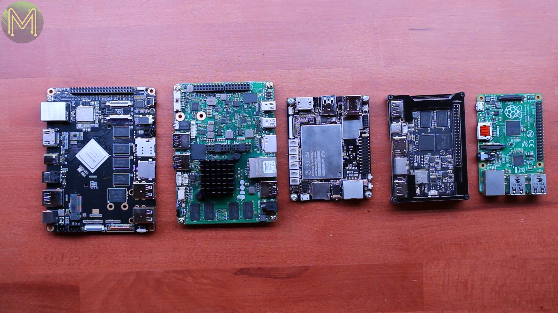
So, the usual HDMI, Ethernet and keyboard and mouse, but remember the smoke Genie from my Orange Pi video? Well I decided to risk it again and use my bench power supply. I connected this inline with a voltage and current logger, which I’ll be reviewing soon.
Then powered it all up. Of course like any male I don’t read any instructions until I hit a problem and discovered that the onboard eMMC hadn’t been flashed.
Installing the O/S
So, a simple matter of fetching the latest testing Debian ISO image, because I like to live on the edge, and burn this to a USB flash drive, which I chucked in to a spare USB port.
I also added a 2.5" SATA disk for some performance testing, which will be included in part 2 of this video.
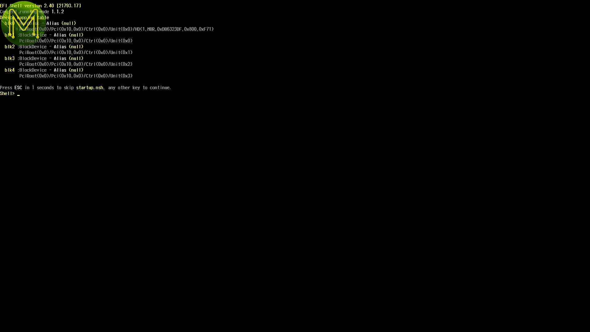
Powering on for the first time I had to go into the BIOS and force a boot of the USB drive.
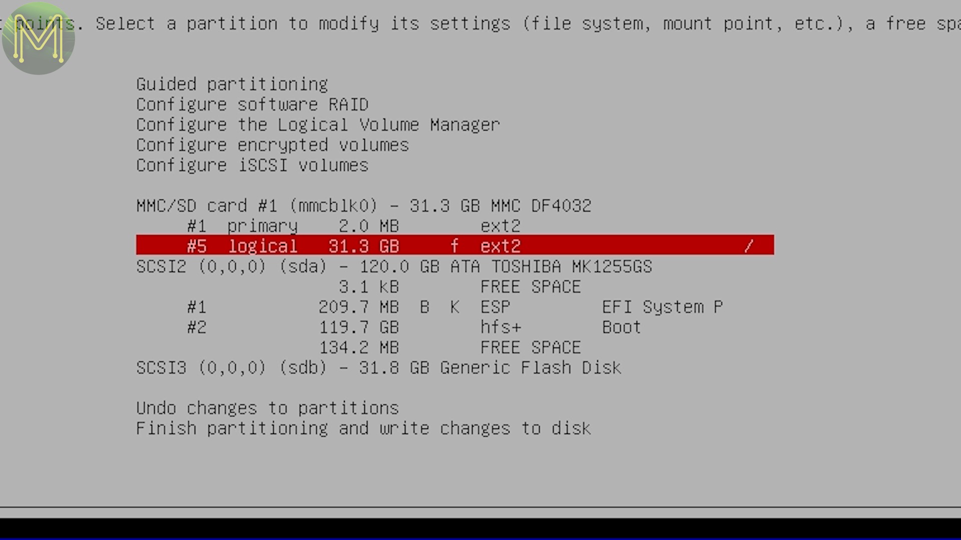
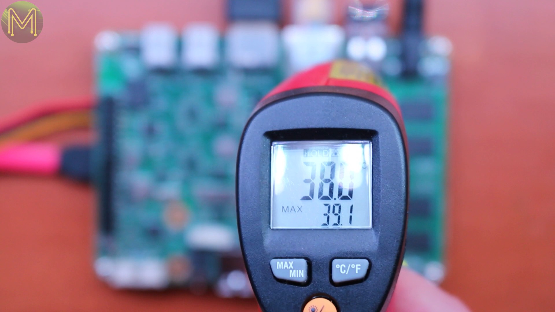
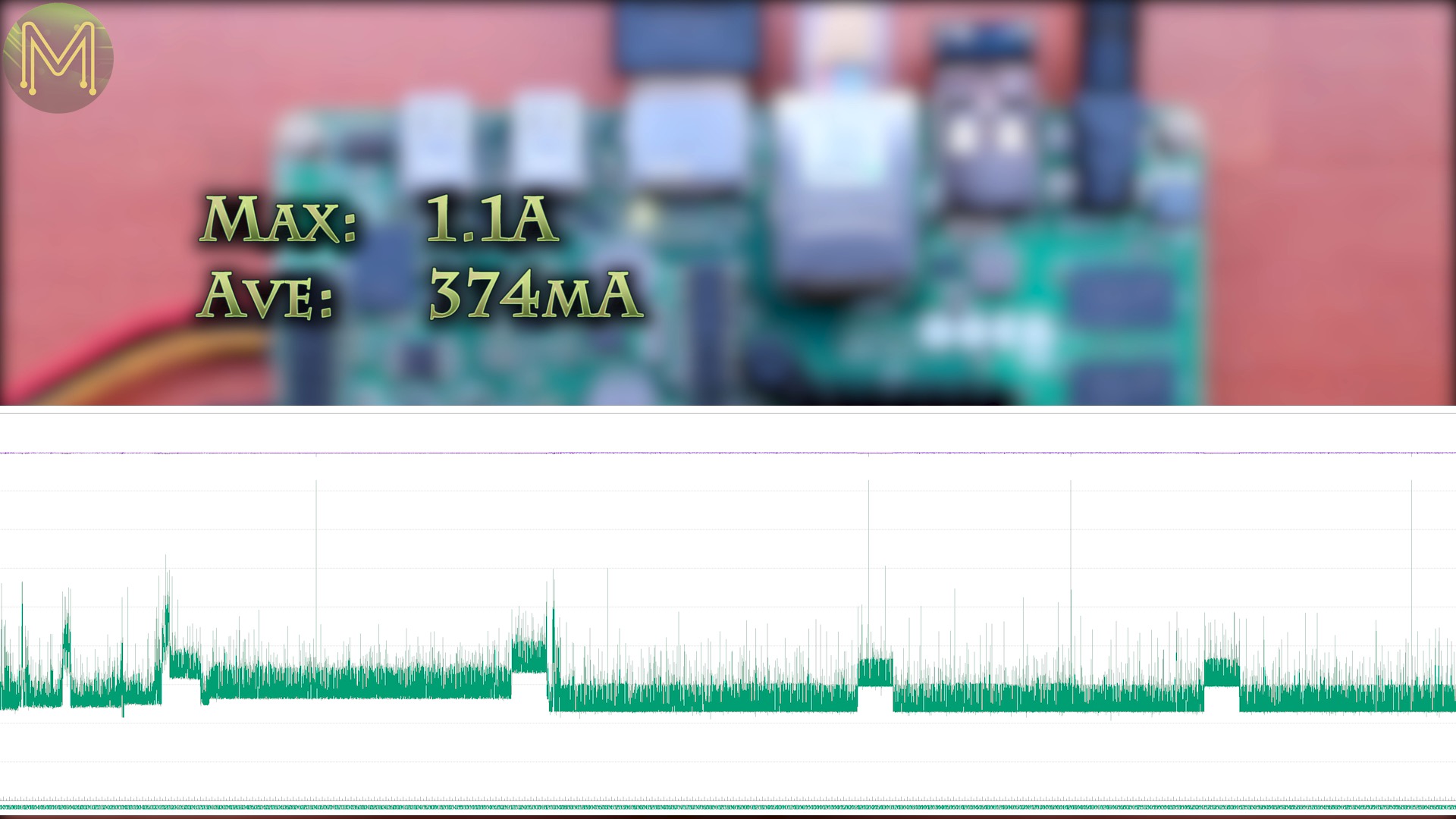
Then the usual Debian installation process. By default, Debian 9 doesn’t have the firmware for the GbE, but you can choose to ignore this step and install the firmware later. It’ll still connect to the network.I left the 2 MB partition intact and created a new one, changing the filesystem type to ext2, because that reduces the number of writes to flash and it’ll last longer.Then once “install” was complete, it booted up into the familiar Debian desktop. Whilst sitting idle, my laser temperature sensor showed a peak of 39.1C. I’d expect this to climb once under load.Whilst booting it peaked at 1.1A and during idle settled down to around 307mA, In suspend mode it went down to 48mA. The SATA hard disk consumes around 20mA whilst powered off, so 28mA is pretty low. The lowest I’ve seen on any SBC so far.Waking up is as simple as pressing the power button on the front.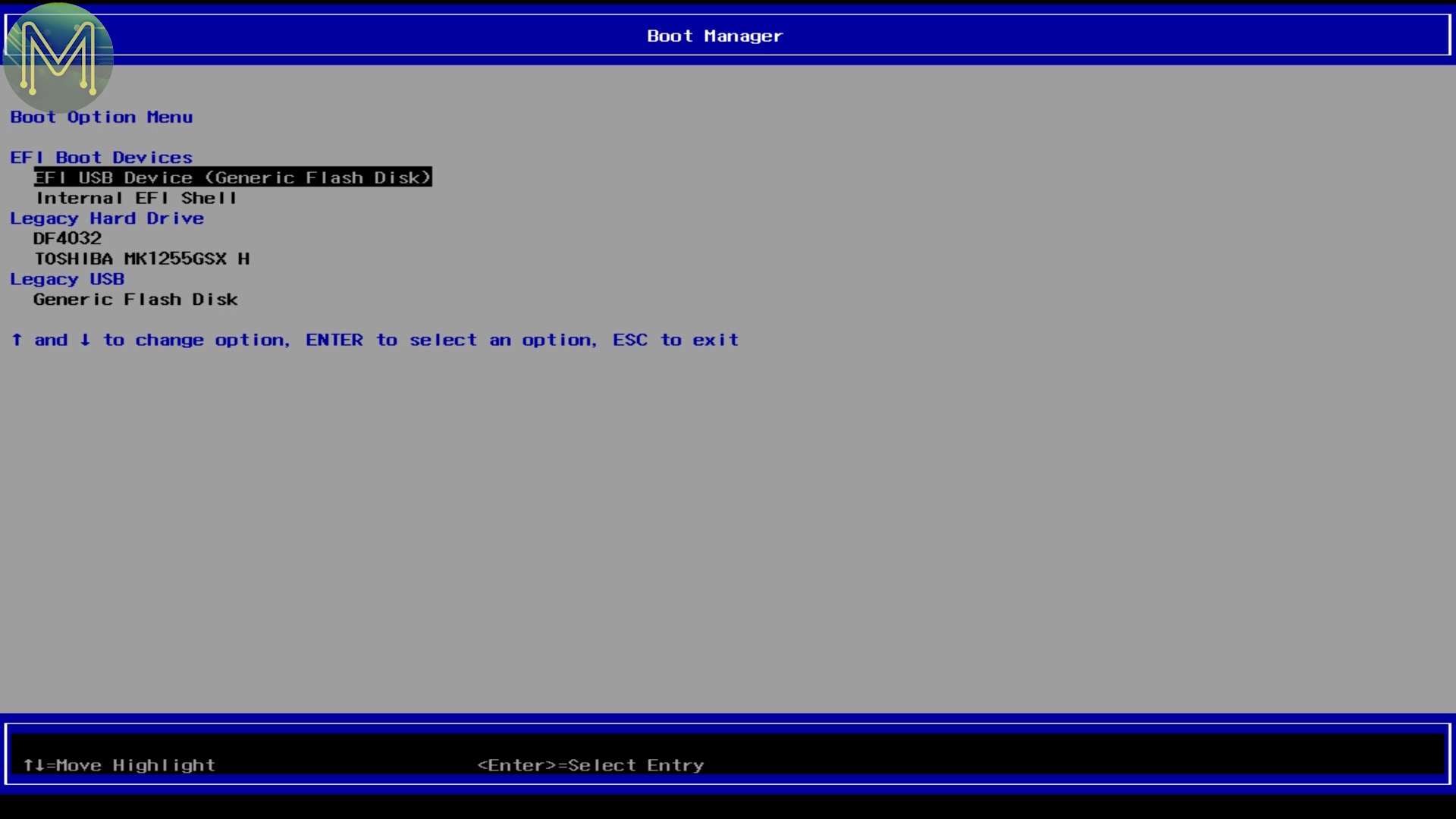


Network Tests
So, the first thing is to install the firmware for the GbE. This is contained in the firmware-realtek package.
apt-get install firmware-realtek
Then the easiest thing is to reboot and you’ll have the new interface running at Gigabit speeds.
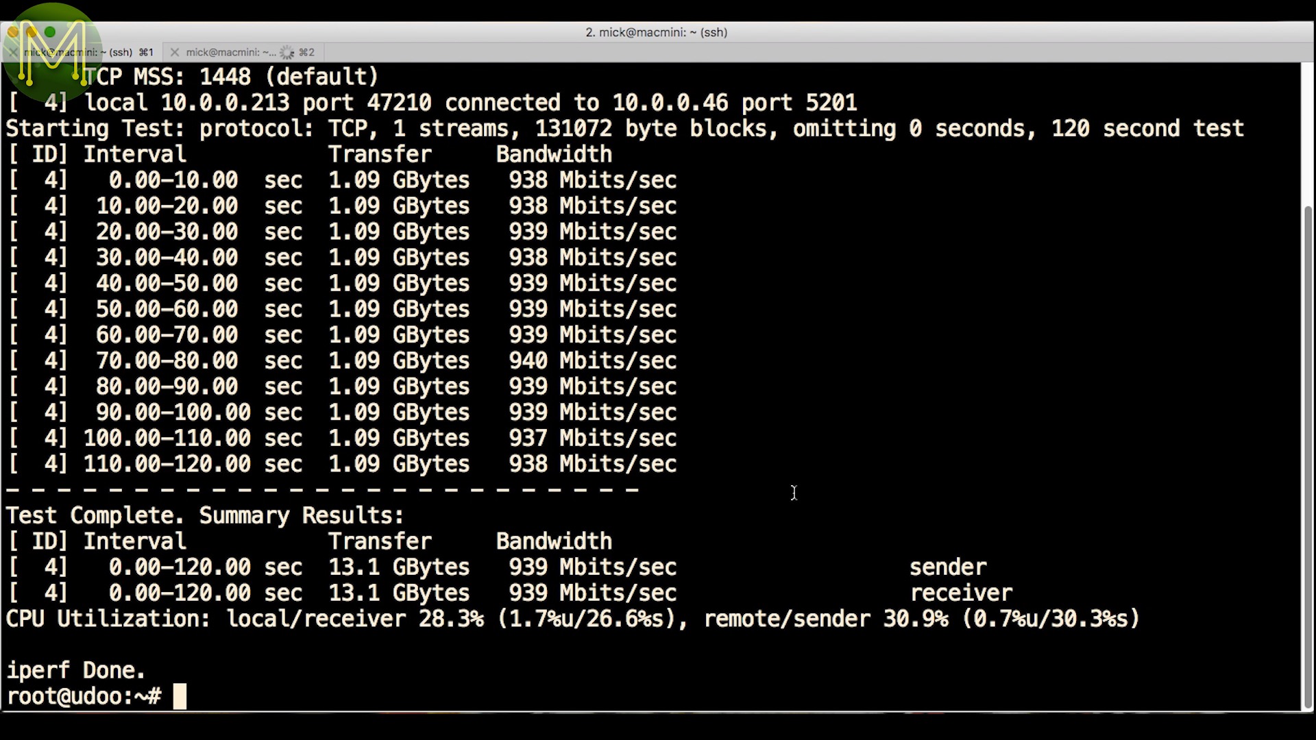
Time for some network tests. The UDOO-X86 is essentially a desktop, so I would have been surprised if there were any issues here. Fortunately, TCP bandwidth was hitting the theoretical maximum of 949Mbit/s and UDP jitter was very low at .092 mS. Nice.

Arduino IDE
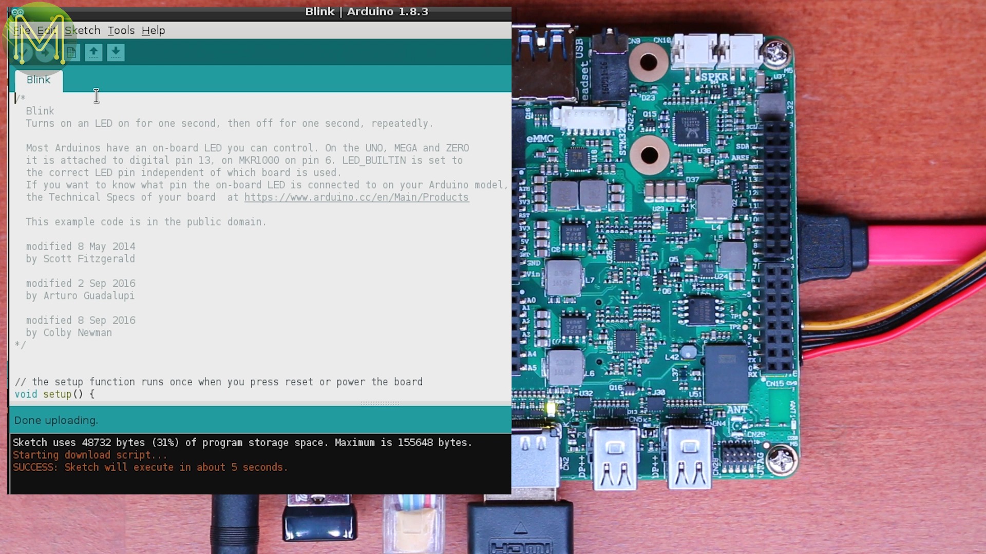
Next - to testing one of the main advantages of this board. So, downloaded the latest Arduino IDE and installed. The first time you run the Arduino IDE it will detect the Intel Curie as an Arduino 101 board and prompt you to install the board package. Man, this is so simple to setup you could do it blind-folded.
Make sure you select the correct board type, and serial port. Then try a very simple Blink sketch.So far I haven’t hit any issues with this board. Everything just works. Nice to see. I was expecting there to be some problems by this stage.
Arduino Testing
Next on to the rest of the GPIO tests. If you want to use any Arduino shields then you’ll need to remove these “pluggy things” first. I used my ILI9341 touch display first up, which fits in as expected. Note, however, that there’s no connector for the SPI header. This is located on the underside of the board. This may cause some issues for shields that rely on this SPI connector.
Then installed the AdaFruit ILI9341 library and loaded up their graphicstest sketch. Which, of course, required the AdaFruit GFX library as well. Nice. It seems everything just works on this board. They’re expensive, but they get the job done.But be careful of some of the AVR based libraries. These won’t work with the Intel Curie without some modification.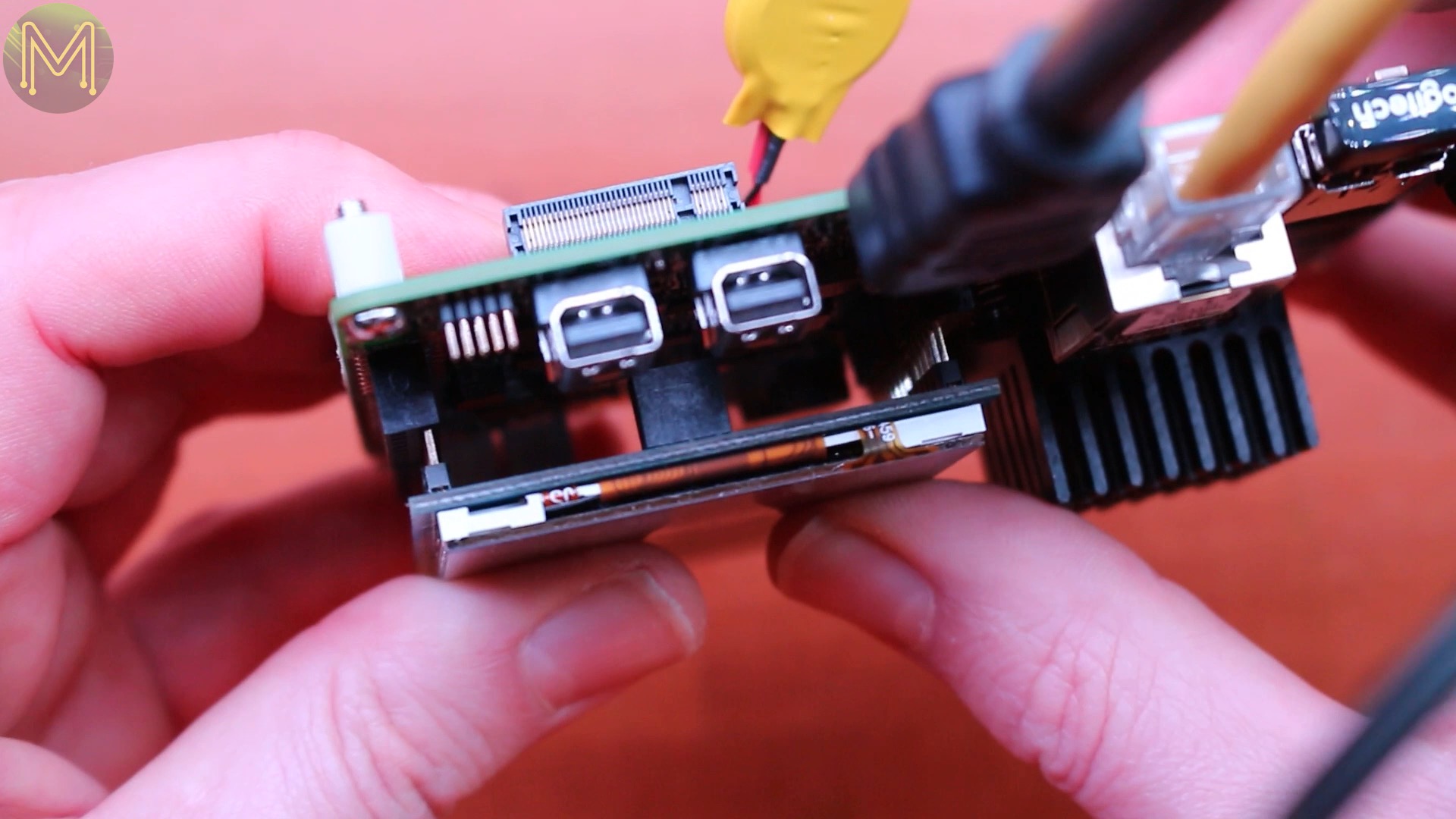

There’s also an onboard IMU on this little sucker, along with a bunch of example code which all worked.
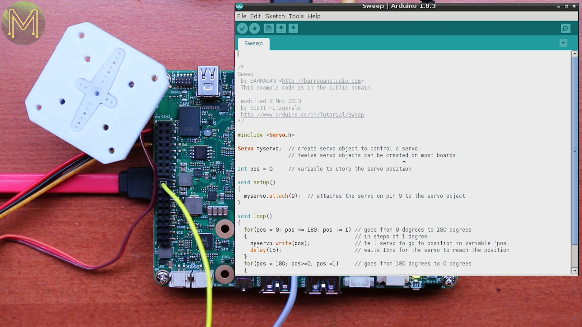
Other examples worked such as a servo sweep test.I know the Curie has onboard WiFi, but I also had a WizFi250 WiFi shield that I wanted to try out. I couldn’t get the Curie talking to it. This board allows you to move the UART to a different serial bus. I used my cheap logic analyzer to find which serial port the Curie was talking on.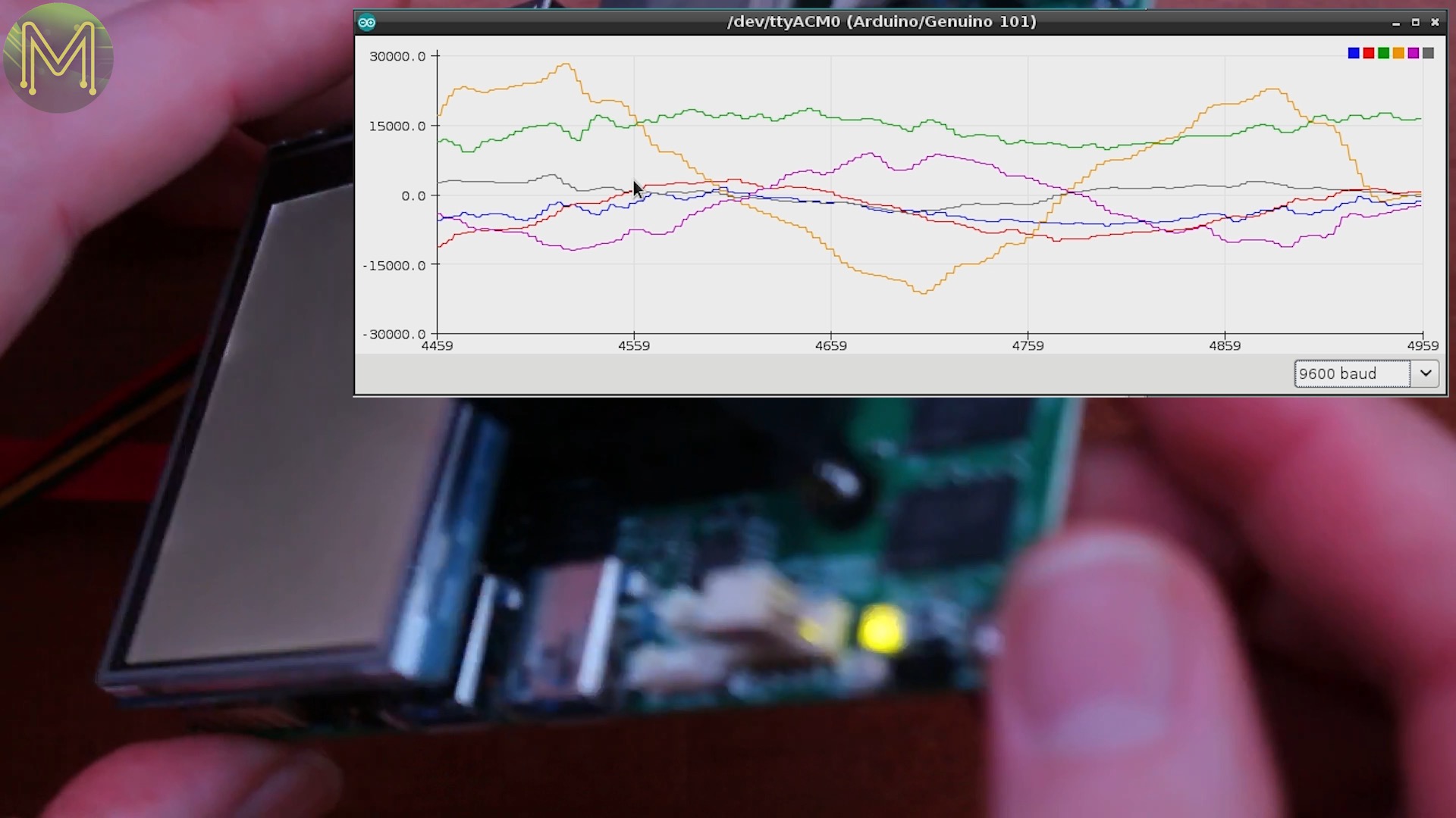
But all I ended up doing was halting communications to the Curie, which forced me to reset it.
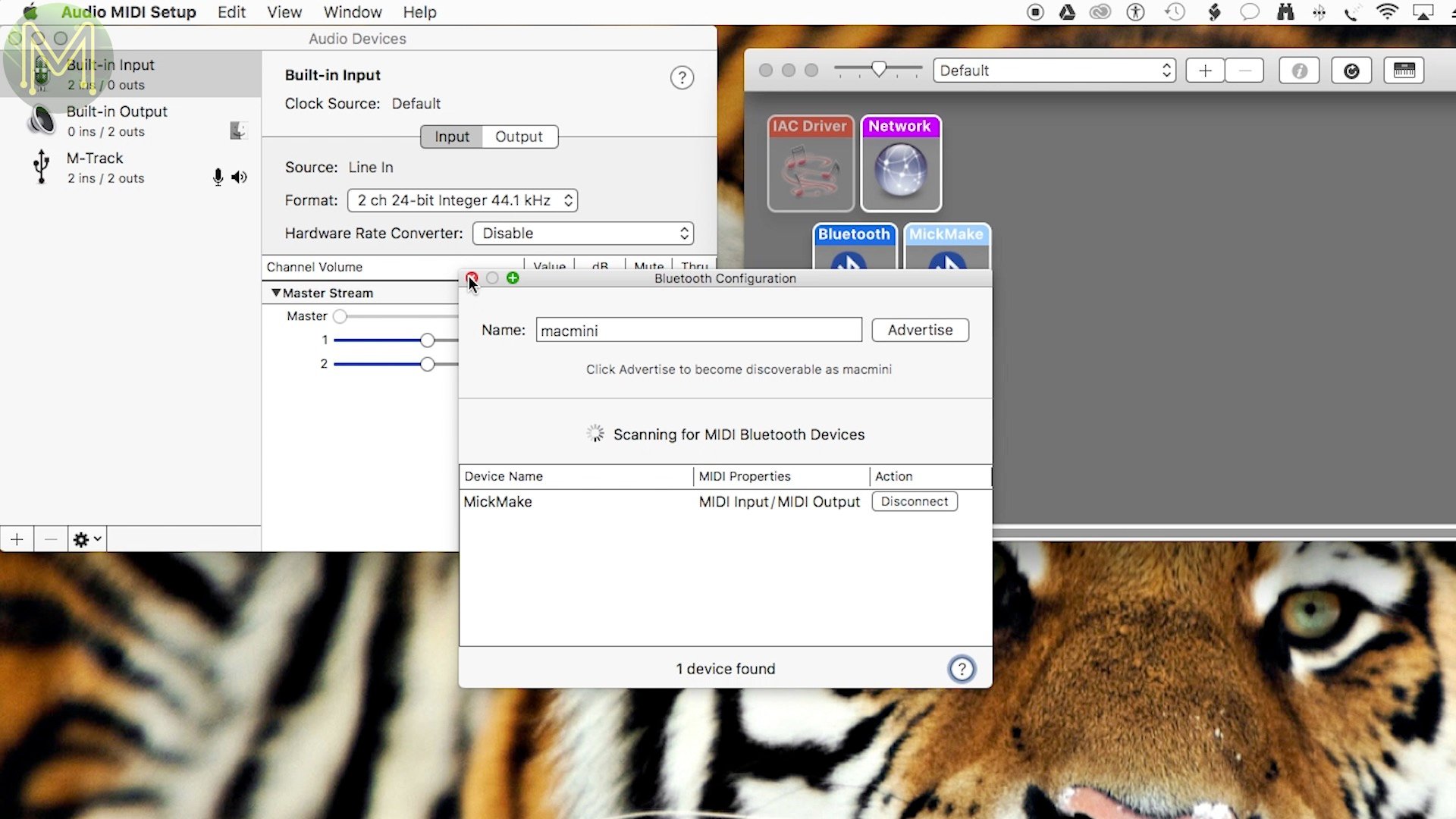
So, what about Bluetooth? Seems the basic Bluetooth scan sketch works without issue, and so does the BLE MIDI example, which creates a bluetooth based MIDI device that plays random notes. Connecting to it from my Mac was trivial.

Arduino Power Control
One of the big advantages to the UDOO-X86 is the ability to power on and off the main CPU from the Intel Curie. So was keen to try this out. They have a nice little section of their documentation showing you how to do this easily enough. All you have to do is send a 20mS pulse on GPIO9.
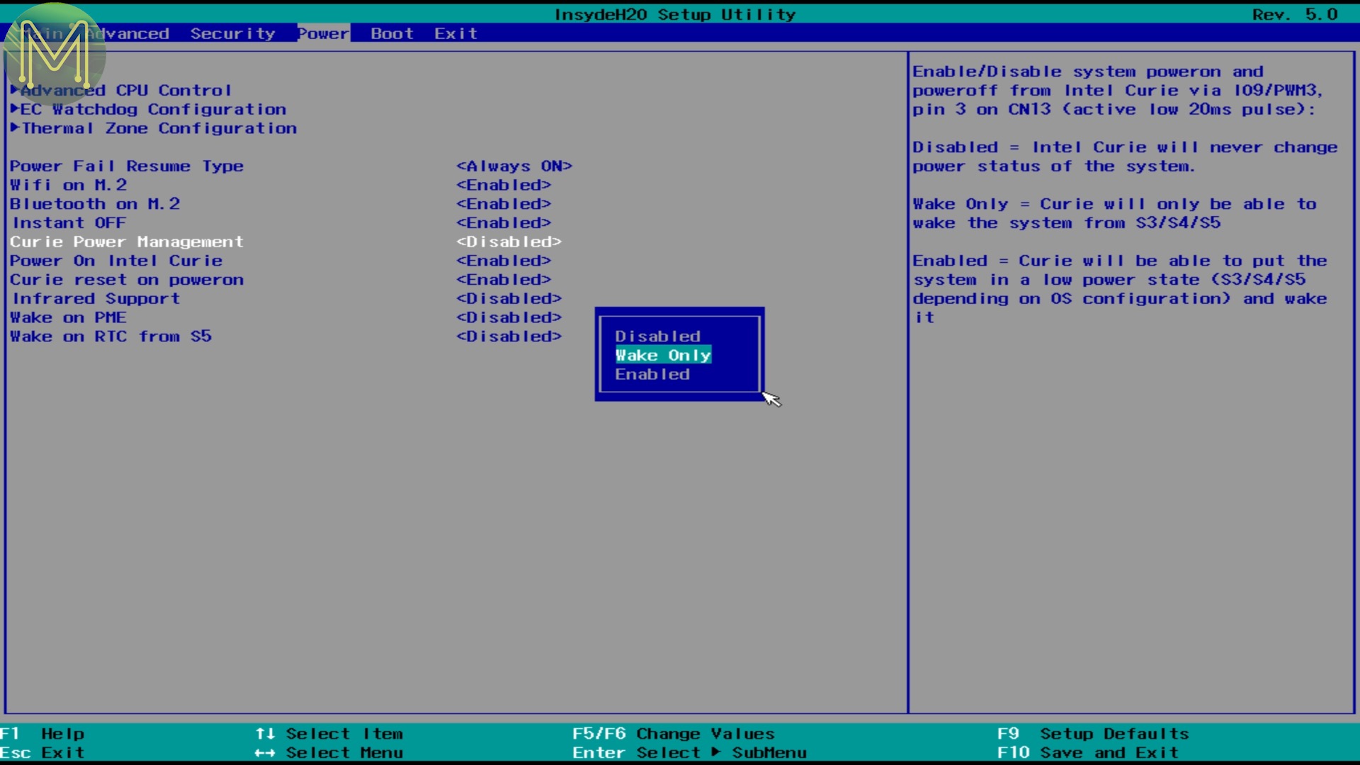
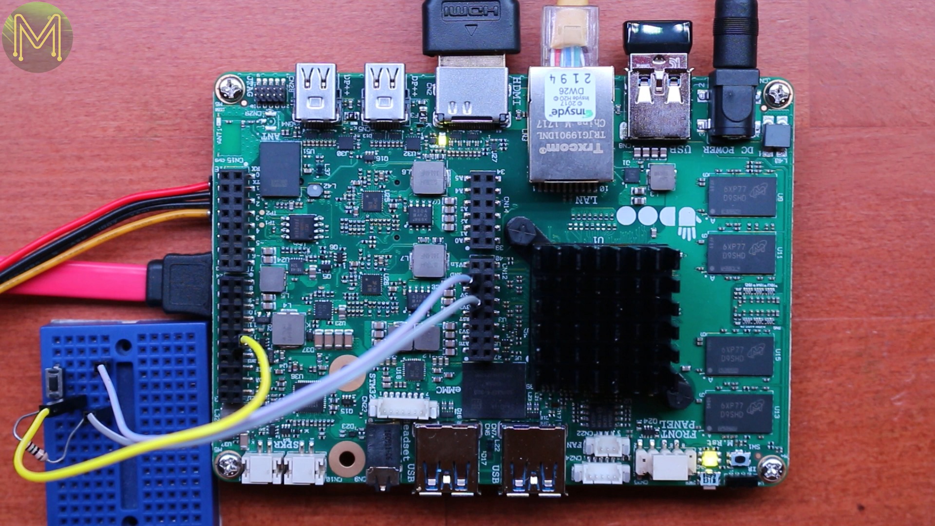
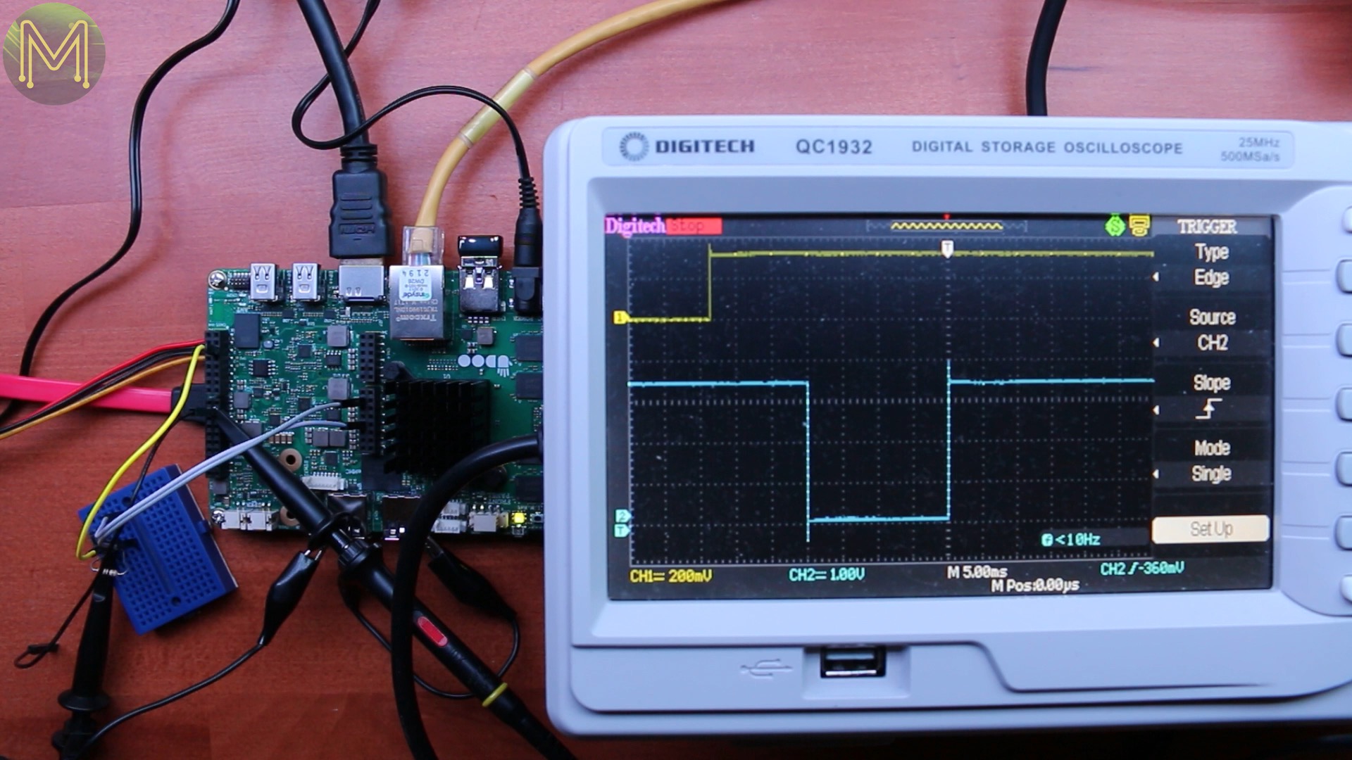
So I enabled the Curie Power management in the BIOS. I wanted to see if I could power on as well as off.I wired up a simple button to power on and off and shutdown the O/S.But as soon as I shutdown it powered back up again. So, I thought I’d try to disable the Curie reset on power on, as that might have some effect.But, nope, still powering on. So, then I set the Curie to only manage waking up, and brought out my crow to check on things. The top trace was me pressing the button. The bottom trace was the Arduino code sending the required pulse out on GPIO9.But, nope, couldn’t wake up the board. The only way was to wiggle the mouse or press the front panel.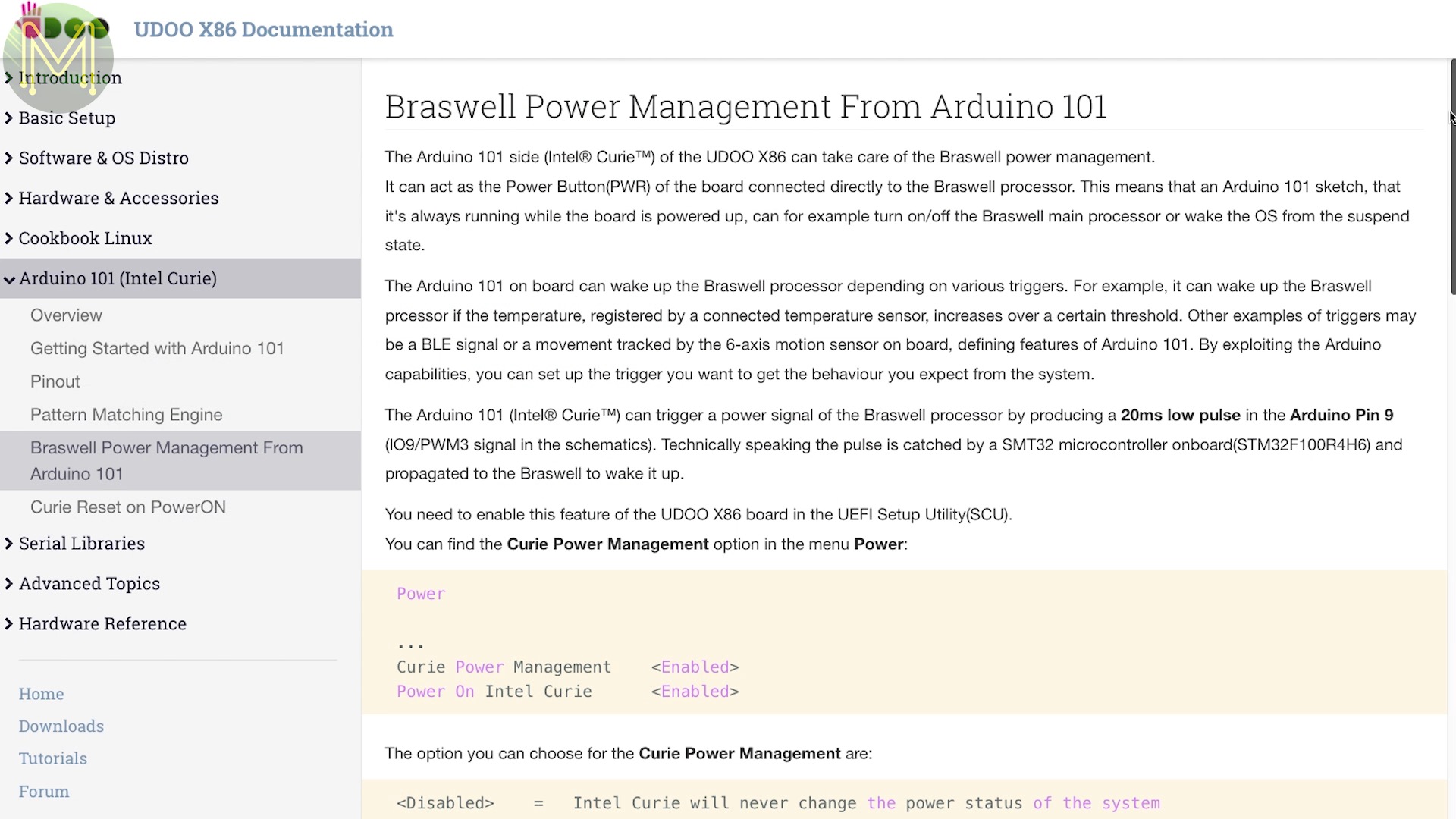
It would seem that when the board is powered down, the Curie isn’t being powered.
After a bit of playing around. I did actually manage to get the board to shutdown using the Curie. So not sure what happened earlier.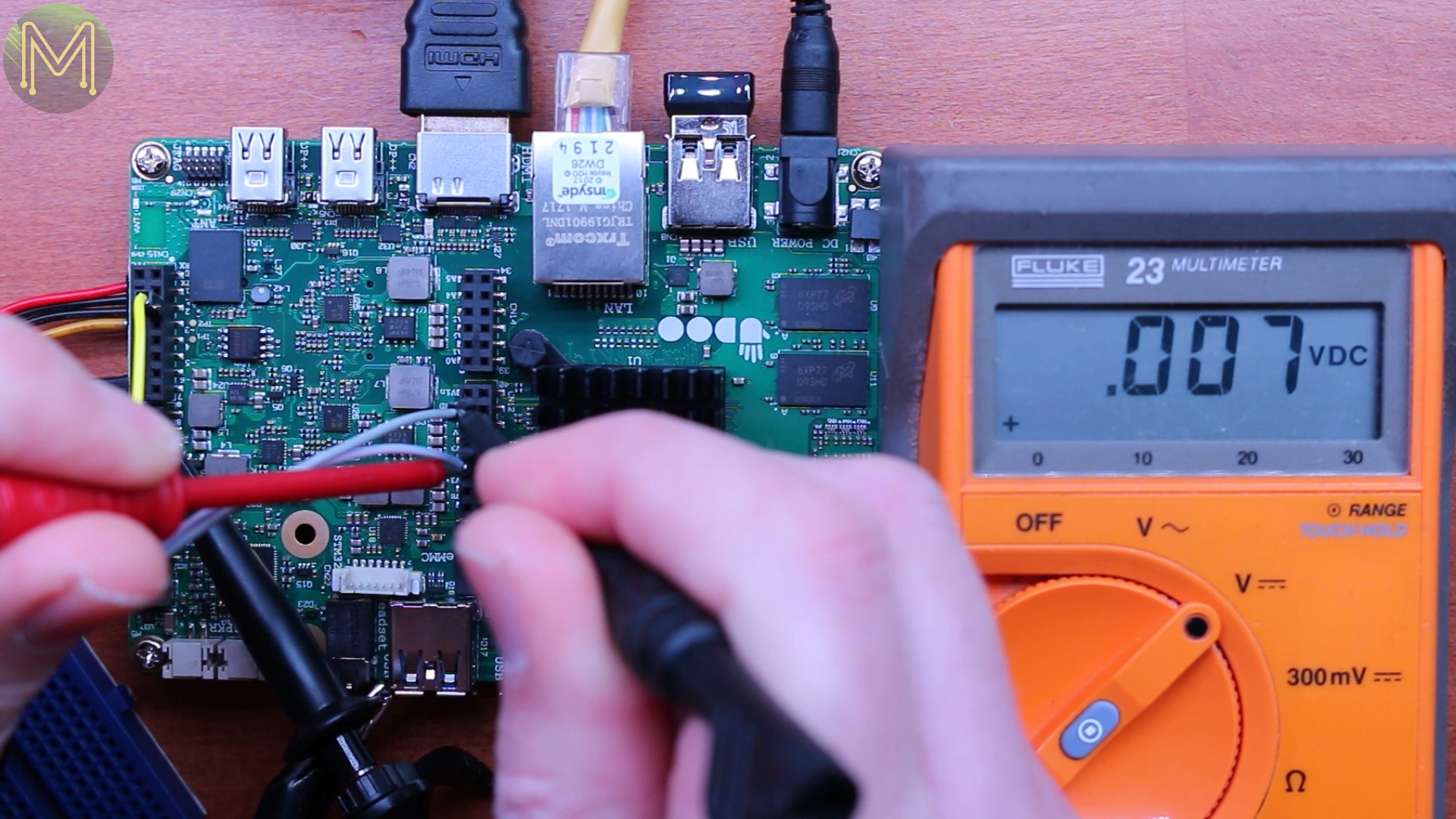
As it turns out there’s a post from the UDOO people about the current firmware not being able to power on the board. As of this video it hasn’t yet been fixed, but looking forward to it.
Simple Power Measurements
Over the course of a couple of days of testing I logged both voltage and current. The maximum current draw I saw was 1.1A and that would have been during power up, with an average of 374mA. That’s not much current draw, but I wasn’t really hammering the CPU. Wait until I get into the performance tests in the next video. The results will be interesting.
Summary
So, what do I think of the UDOO-X86? Well, from the electronics Maker perspective it’s a board that does everything as advertised.
Apart from the Curie Power Management issue I couldn’t fault this board at all. The board is very well designed and they have made available all schematics & documentation. They are also making every effort to support the community which seems to be growing well. So far, I haven’t seen many complaints.
In Part 2 of this video I’ll be taking a look at the performance side of this board as well as running alternative Operating Systems and upgrading the BIOS.