Nano Pi M4: Can an SBC get any better? - Review
The NanoPi M4 has been around for some time now. However, this is one SBC that I hadn’t gotten around to reviewing. So, what makes this board so special? Let’s find out.
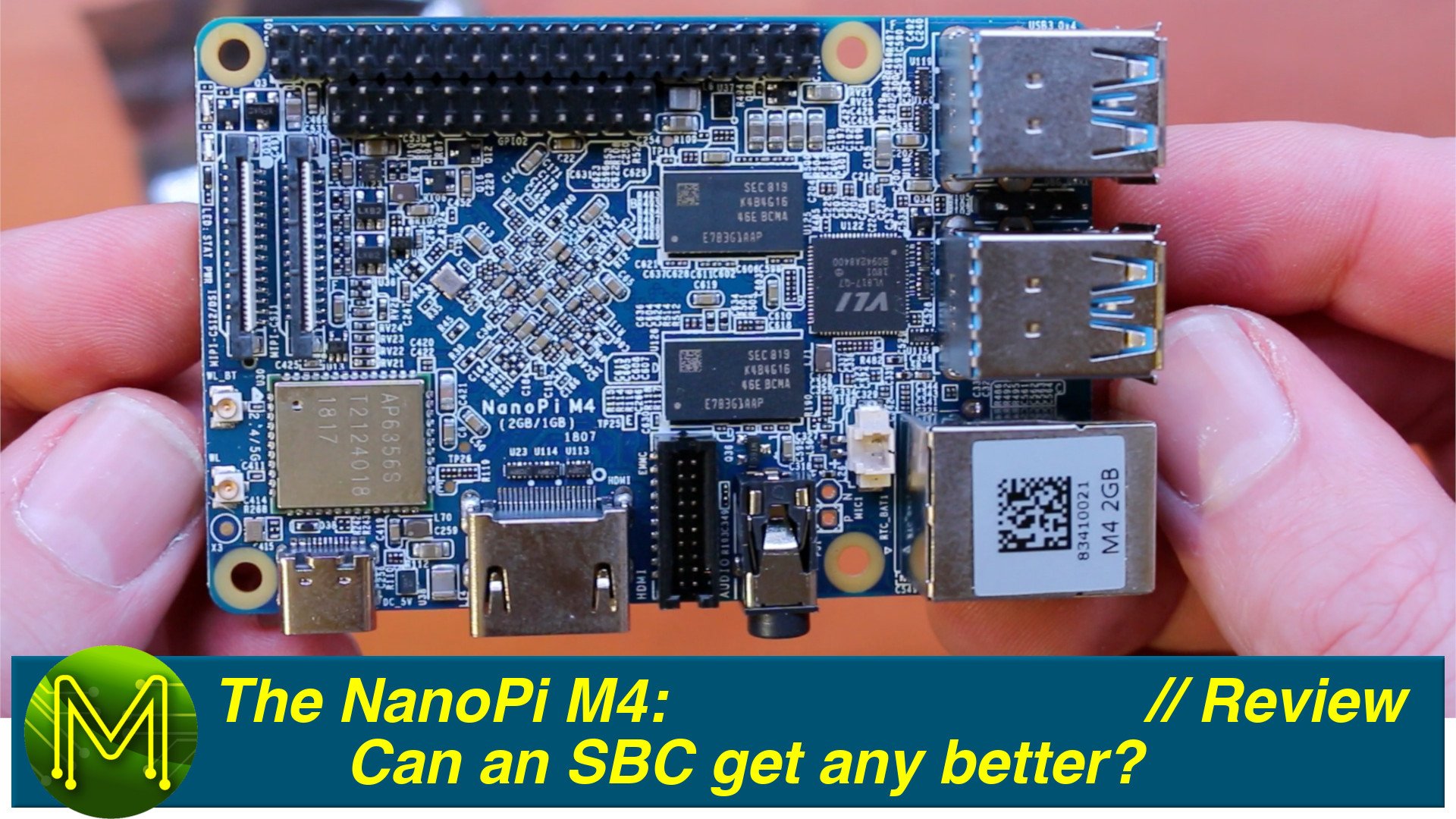
Unboxing
So, over the last 3 years I have been given quite a few SBCs to review, but there’s times when I just go off and buy them myself. The NanoPi M4 was one such board and it set me back around 93 Kangaroo bucks.
So, what have the friendly guys given us on this SBC? Starting from the top right working clockwise… – Top01 - A bunch of ESD protection ICs.
– Top02 - Even more ESD protection and a ViaTech 4 port USB 3.1 hub, supporting up to 2.4A per port, but looking at the datasheet, it seems like FriendlyARM haven’t allowed for this on the power side.
– Top04 - One half of the 2G DDR3 RAM, but you can also get 4G.
– Top05 - MosFET controlling power to the RAM when in sleep mode.
– Top06 - Uh yeah, even more ESD protection.
– Top07 - DC to DC converter for the GPU accessible over I2C. As I mentioned in my NanoPi NEO4 review, all the FriendlyARM components have identical part numbers. So U38 is the same on that SBC.
– Top08 - D38 is more ESD protection. There’s also the AP6356 WiFi and Bluetooth module.
– Top09 (U13 - RT9193) - U13 is a small 3.3 to 3v LDO regulator from Richtek.
– Top10 (U36 - XC6219B122MR) (U9 - RT9193) - And a few more regulators splattered around the place. U36 provides 1v power to one of the MIPI-CSI headers. U9 provides 1.8v for the SoC.
– Top11 (U123 - XC6219B122MR) (U9 - RT8010GQW) - U123 is another regulator for the second MIPI-CSI. And U9 is another Richtek DC step-down providing 0.9v to the SoC.
– Top12 - Q3 is a MosFET controlling 5v power to the SoC via the PMIC.
– Top13 - And interesting way of mounting LEDs, but hey it works.
– Top14 (U37 - SYR837) - U37 is a DC buck converter providing 5v for the SoC.
– Top15 - And a bucket load of 0201 SMDs.
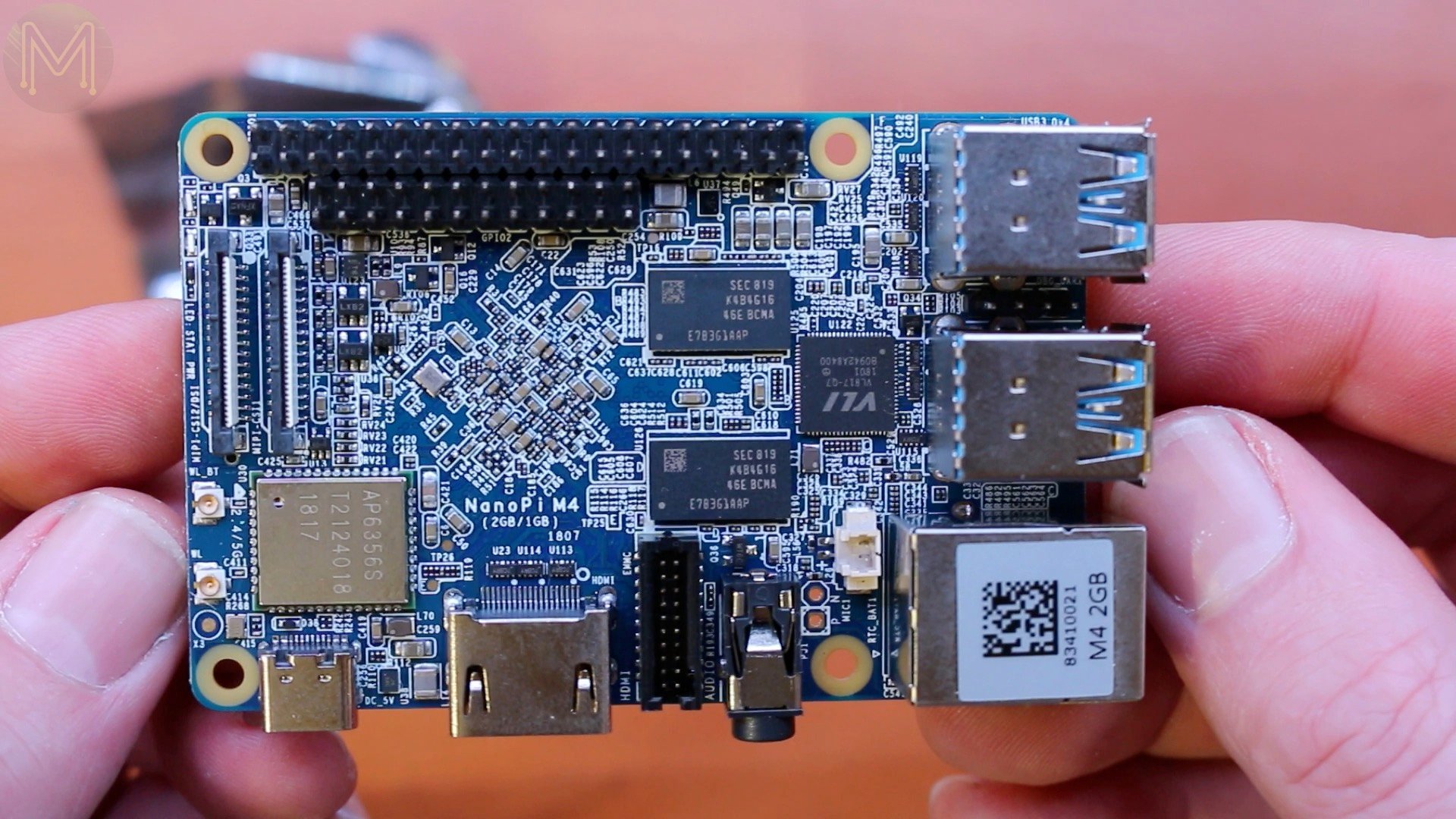
There’s not a heck of a lot of action on the top side. However, on the flipside we have…
– Bottom17 - Q44, yeah another MosFET.
– Bottom18 - And even more of the buggers.
– Bottom19 (U94 - TXS0102) - U94 is a 2 channel logic level converter from TI that I am using on my wyrks-UPS boards. This provides translation from the SoC’s 1.8v, to 3.3v on the GPIO header for I2C.
– Bottom20 (U110 - MP2143DJ) - U110 is yet another 5v to 3.3v DC buck converter.
– Bottom21 (U35 - RT9041B-10GE) (U11 - RT8010GQW) - U35 is another LDO providing the 0.9v juice for the SoC.
– Bottom22 (U11 - RT8010GQW) - U11 is another DC buck converter providing power for SoC’s GPIOs.
– Bottom23 (U28 - FUSB302B MPX) - Yet more ESD protection. And U28 is a programmable USB Type C controller with PD functionality. We’ve seen this one before as well.
– Bottom24 (U2 - RT9193) - U2 is yet another LDO from Richtek. Heck, these are everywhere.
– Bottom25 - F8 is an SMD poly fuse.
– Bottom26 (U29 - ALC5651) - Aand here we have the ALC5651 audio codec. Nice little chip.
– Bottom27 (U19 - RTL8211E) - And U19 is the gigabit ethernet driver. These semis are as common as a plumber’s crack.
– Bottom28 - Yup, more ESD protection.
– Bottom30 - And more SMDs. I’ve forgotten why I took these photos, but there you go.
– Bottom31 (U41 - RT9724GQW) - U41 provides power control over the USB ports.
– Bottom32 - And here we have the inescapable RK808 PMIC. It’s big, because it does lots of stuff. Really, you can’t get away from having this onboard when using any of the RockChip SoCs.
– Bottom33 (U101 - RT9724GQW) - U101 is another USB PD controller.
– Bottom34 (U16 - RT9193) - And here’s yet another RT9193. This makes it the 5th we’ve seen on this board.
– Bottom35 - And… yeah not sure why I took this photo either. I’m sure it’ll come to me.
Setup
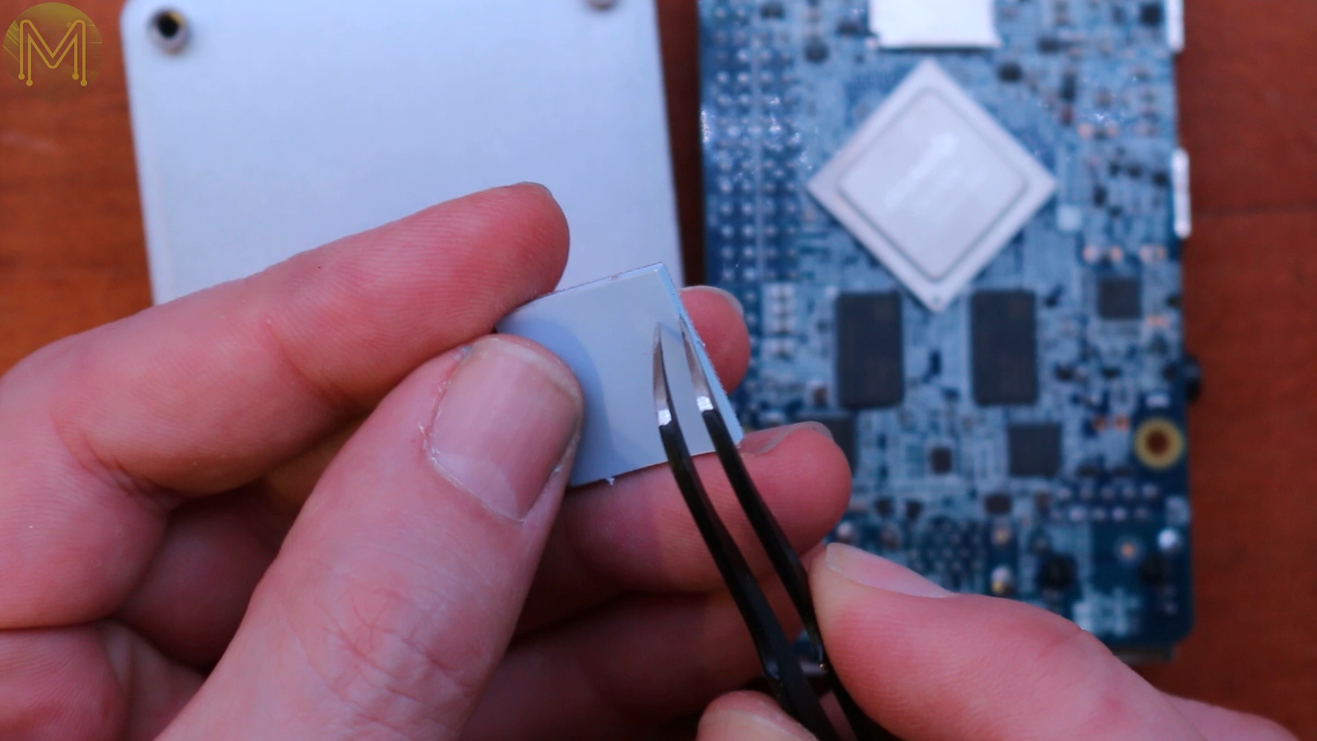
So, before I get started on my tests I need to whack on the default heatsink. If you’ve watched any of my other review videos, I often use my Uber heatsink as I found that it performs the best out of any I’ve used. It’s clunky, but gets the job done.
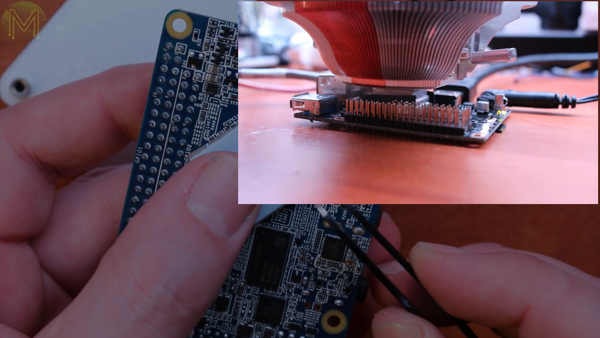
Ideally, I shouldn’t use this blue sticky thing, because it doesn’t transfer heat well enough, but since I’ve already done a swag of benchmarks on the RK3399 in previous videos, I won’t be repeating them here.
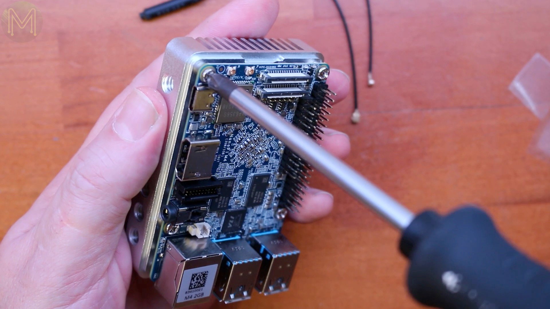
When you’re screwing up the heatsink to the PCB, always make sure to alternate the tightening up of the screws. Doing this avoids applying any torsion forces to the PCB.
I also bought an eMMC module that I’ll be using to load a couple of operating systems, to see where they are at now.
Then there’s the WiFi and Bluetooth antennas. I won’t really be testing them in this video, because we all know they work, but always good to add them in anyway.
Then we have HDMI, Ethernet, keyboard and mouse.
And hang on, before we add the juice…
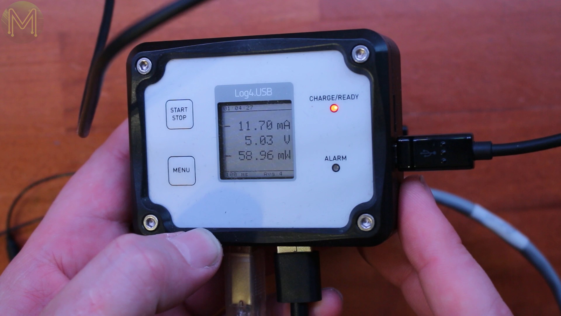
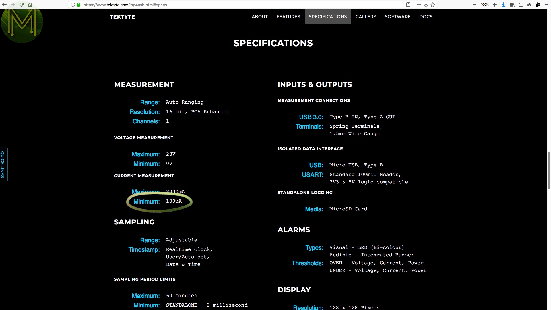
I will certainly be monitoring power consumption on this little baby with my handy usb power logger. As you’ll find out later, it has some pretty decent low power options.
Firmware
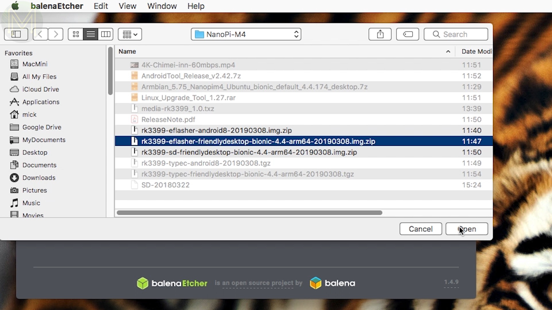
OK, now that we have everything all connected up, time for the firmware… I downloaded FriendlyARM’s official M4 releases:
- Friendly desktop bionic for eMMC
- Android8 for eMMC
- SD based Friendly desktop
- And also using their eFlasher
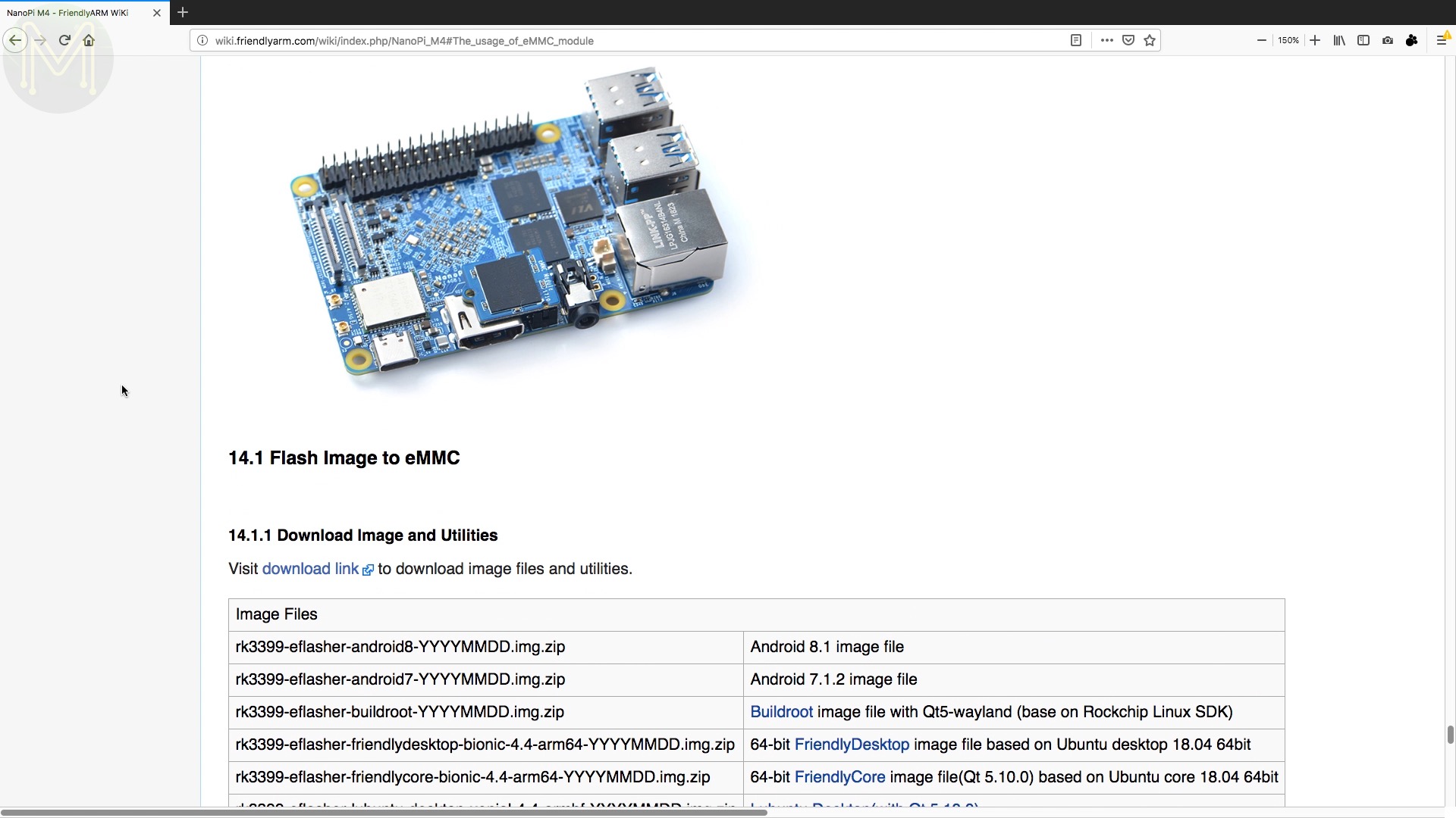
One of the biggest issues with SBCs that have eMMC onboard is having to update the firmware on them. For some reason SBC companies just don’t seem to get it right and make it really difficult for you. However, if you want a very simple and easy way to update your firmware, then FriendlyARM provide their eflasher. This is essentially an SD bootable image that contains an O/S image and a small program that flashes this to the eMMC. It really is dead easy and if you’re someone who never reads instructions properly in the first place, like me. You actually can’t go wrong with it.
Once burnt, chuck it into the SD slot. Unfortunately, this is one of those missile based SD slots. You know, the ones that blast your SD card across the room.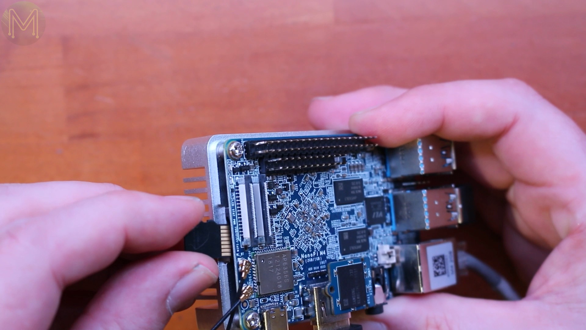
BootingAndroid
Next just power up the board… and you’ll be greeted with the eFlasher screen. Told you it was easy.
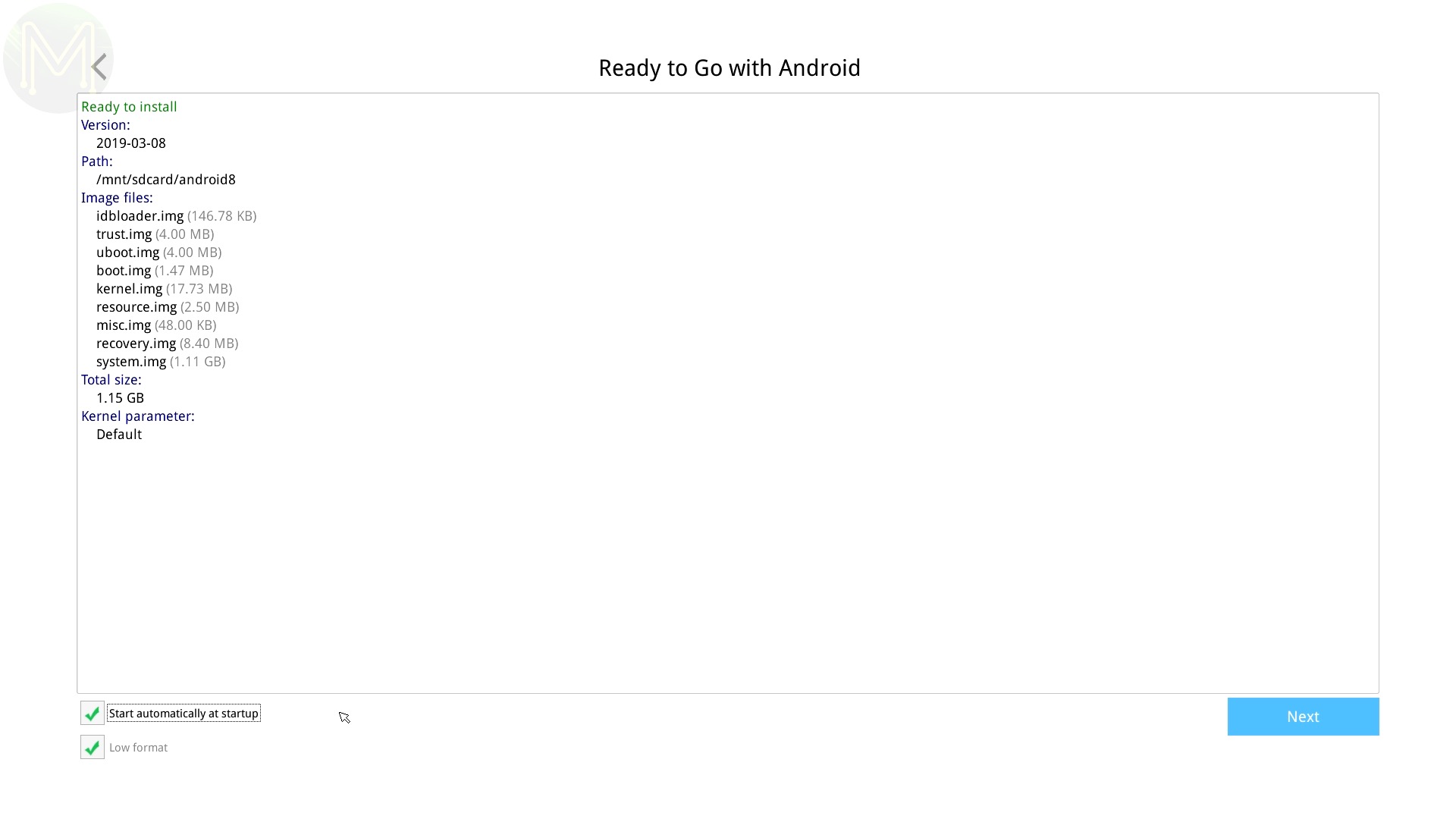
The eFlasher allows you to easily backup and restore eMMC based firmware. And if you have a USB drive you can backup your current firmware to that. Nice. All they need to come out with is a USB bootable eFlasher and we can kiss the old SD card goodbye.
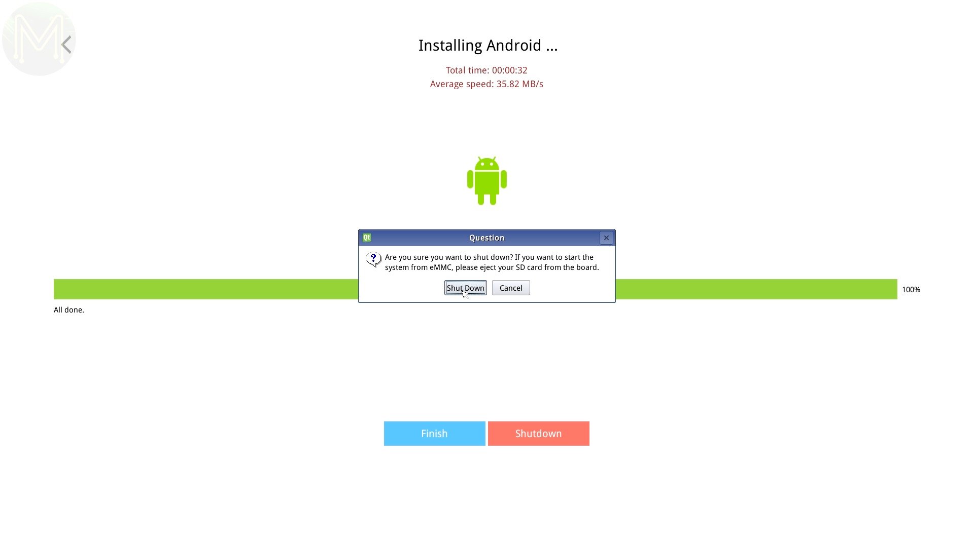
Once it’s finished. Power off and remove the SD card and re-apply power.


Since it’s an Android image, the first bootup it’ll do a bit of fluffing around and you eventually get to your Android desktop thingy… Do you call it a desktop? Dunno.
So poking around, it’s pretty obvious that FriendlyARM are one of the best at delivering software that works.
And they even have support out of the box for accessing the RTC based low power modes. Oooh nice.

With this you can a time to wake up and it’ll sit there counting down unti wake up. If you click on power off, it’ll shut down and power back up again when the timer expires. This is the first SBC I’ve seen providing this functionality working out of the box.
When I pushed the SBC into sleep mode, it got so low that the USB power logger had trouble ranging, as it can only measure down to 100uA. So this board can be pushed into some pretty extreme sleep modes. Nice.
You also have access to a watchdog, which is essential if you want to ensure reboots happen properly on application hangs.
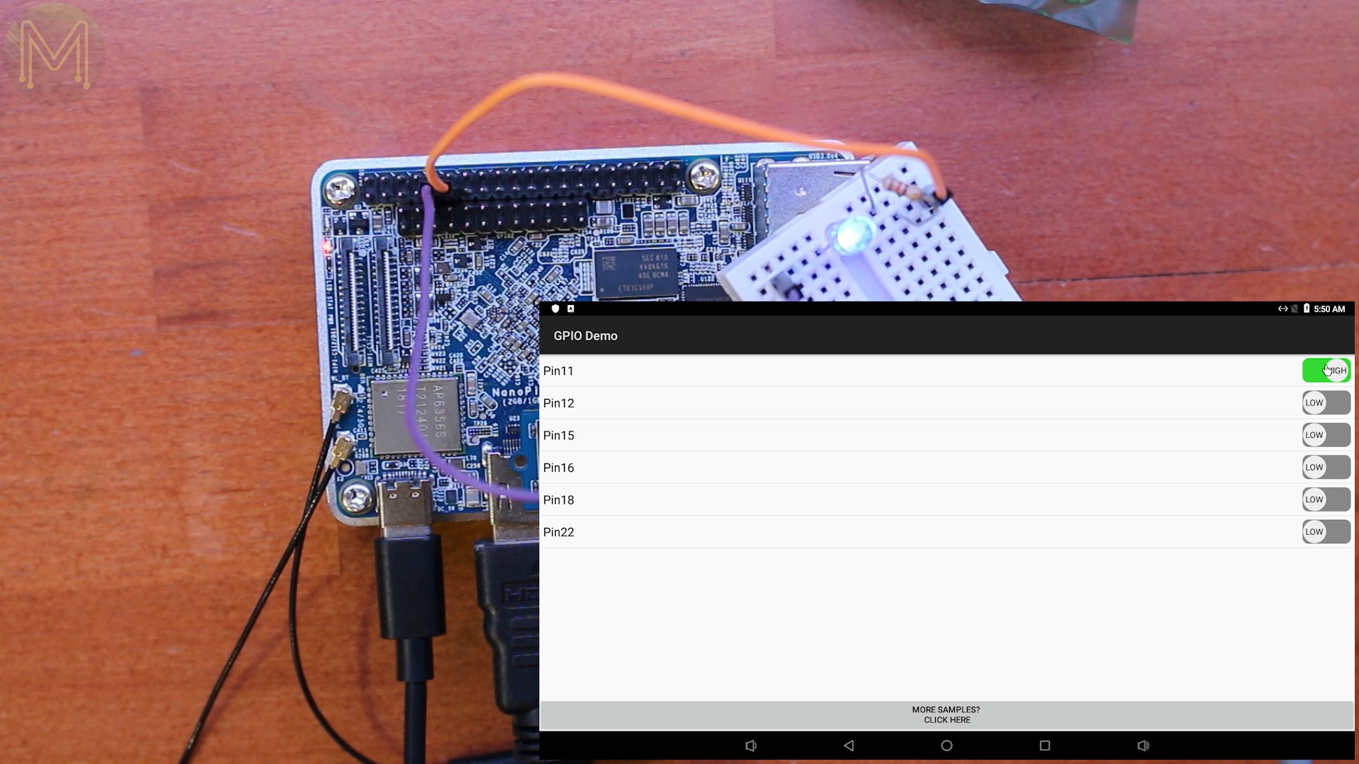
And you also have access to GPIOs. Quite a few companies have this option on Android, but none have managed to provide it working out of the box.
So out came my blue LED.
Hold Cow, batman! It works! Is there anything that doesn’t work?

Let’s try playing a video. I loaded up FriendlyARM’s 4K demo video onto a USB flash drive. Which played pretty smoothly, no jittering or drop-outs.
For any vegeterians out there, I apologize, but every time I see this bit of the video I get hungry.

So, this 4K video is being down-sampled to 1080p, what does it look like on a 4K screen?
Unfortunately, I don’t have a 4K recorder. So, you’ll have to make do with a shaky hand-held shot of my son’s 4K TV.
The video was smooth and responsive. No complaints here.

BootingBionic
All right, so enough of Android. Let’s get into an O/S that the 6 million dollar man would be proud of… This time with Ubuntu Bionic. Actually, it was FriendlyARM’s modified version, but the same thing.
I followed the same process as before, burning the whole shebang to SD card, booting, and reflashing the eMMC with the image. Then shutdown, took the SD card out, and powered back up again.
Easy!
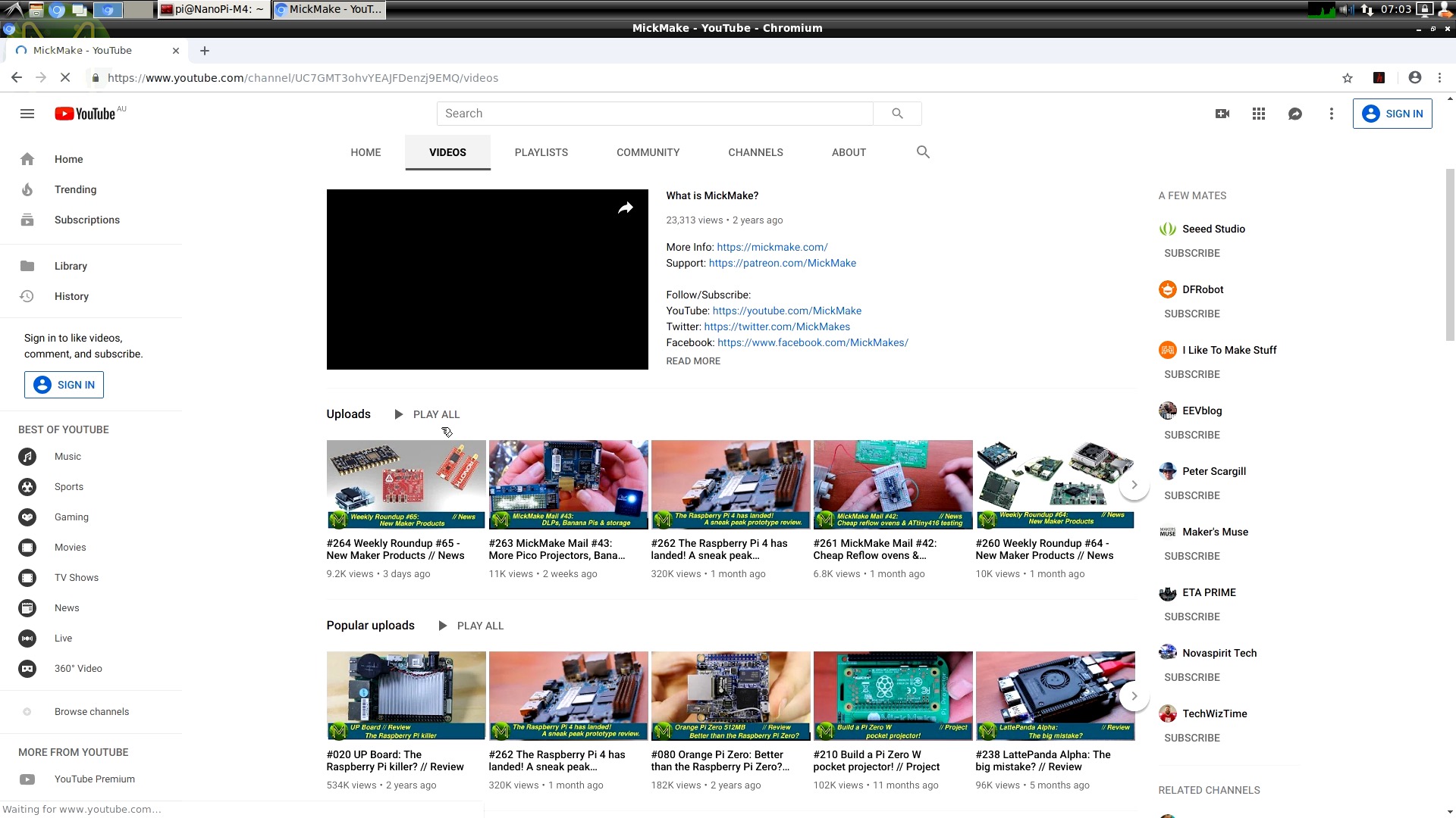
So, I thought I’d try a few subjective tests, just to see the overall desktop experience. It was all pretty snappy, with Chromium loading up my YouTube channel and playing a video without issue, but you know YouTube will scale the video down depending on a lot of factors.
The demo video that’s included on the O/S image had a pretty snappy playback. The fact that they included a video shows that they have spent a fair amount of time making sure it does work.
Next the 4K demo video that I have on USB flash drive. Wonder how this will go?
Holy cow, I’m getting hungry again. So, yeah. This board has no issues at all with a 4K video.
Now, I know that the FriendlyARM guys support Armbian financially. This is a big win all around for everyone, because not only do FriendlyARM end up with better software for their SBCs, but you get a much more stable platform. You can see this when you login to the O/S. It has a familiar feel to it as it’s just Armbian re-badged.

So, one thing I didn’t try last time is OpenCV. FriendlyARM provide a GitHub repo that gets you up and running pretty quickly.
And building the examples was straight-forward.
And so was running the examples. Like smile detection. Er OK. That demo didn’t quite work, but the whole OpenCV API was working without issue.
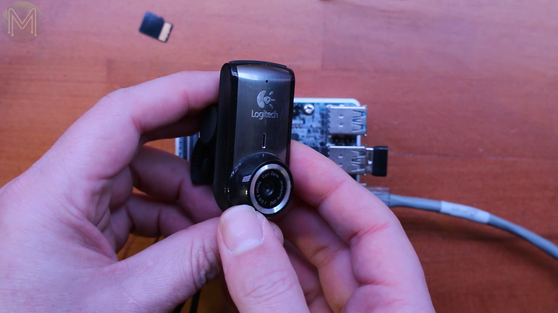
Now I did run into an issue with my 1080p web cam.

It’d lock up completely and vanish off the bus, but this is actually an issue with the webcam rather than anything on the M4. I actually have the same issue on a standard Linux desktop.
Switching to a lower res, better supported camera worked without issue.
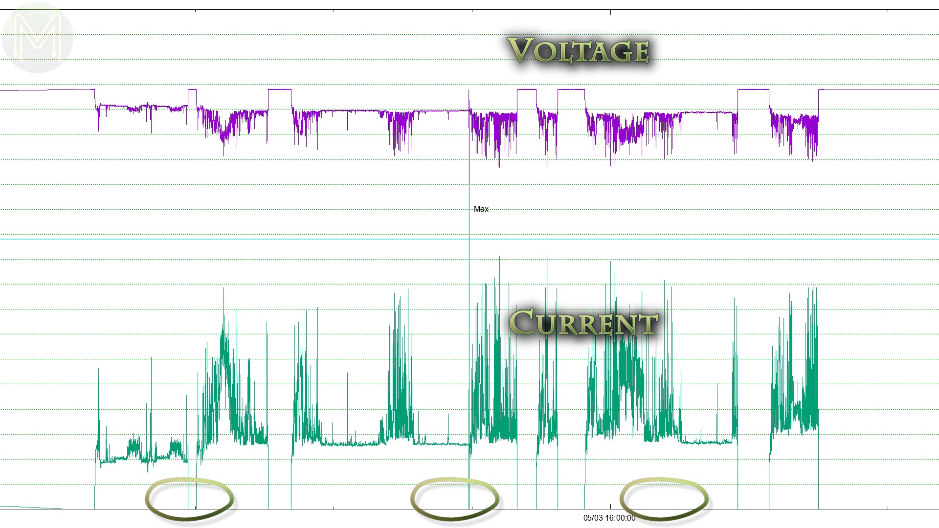
So, with all that mucking around, what did the power consumption look like? Pretty decent really. I saw a peak of 3.2A with an average of 663mA. This is inline with all the other RK3399 based SBCs out there. So no surprise.
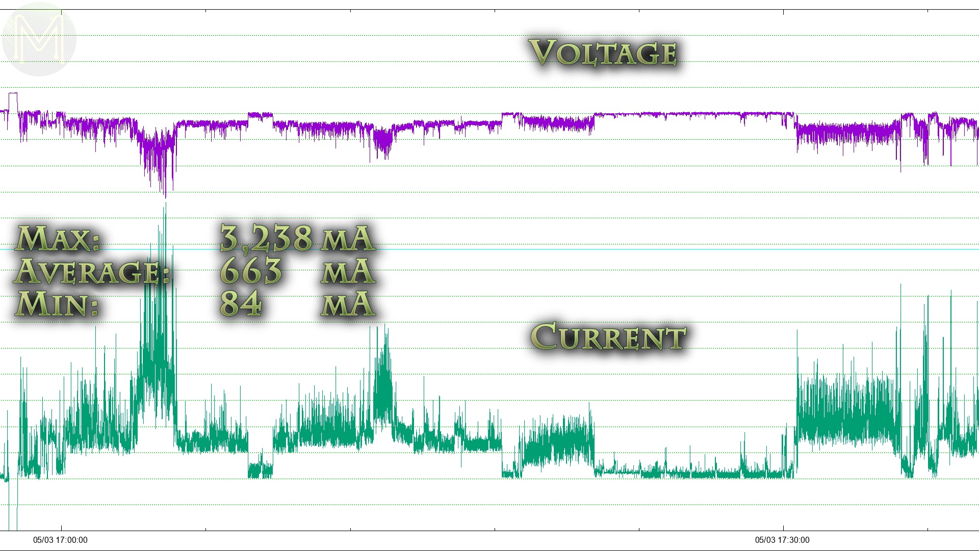
- Max: 3,238 mA
- Average: 663 mA
- Min: 84 mA
OK, so we had the capability to use the on-board RTC to wake the main SoC from sleep mode on Android. Can we do it on Linux?
Turns out there is an executable called rtcwake, which allows you to both set a wake up time and push the SoC into several sleep modes.
The NanoPi M4 supports only a handful of modes. Freeze mode freezes all processes, suspends devices allowing a faster wake from sleep, but still consumes a fair amount of juice. I saw this mode getting down to 345mA peaking at 431mA. Not that low, but as you can see from the graph, there were no processes pulling the CPU load high.
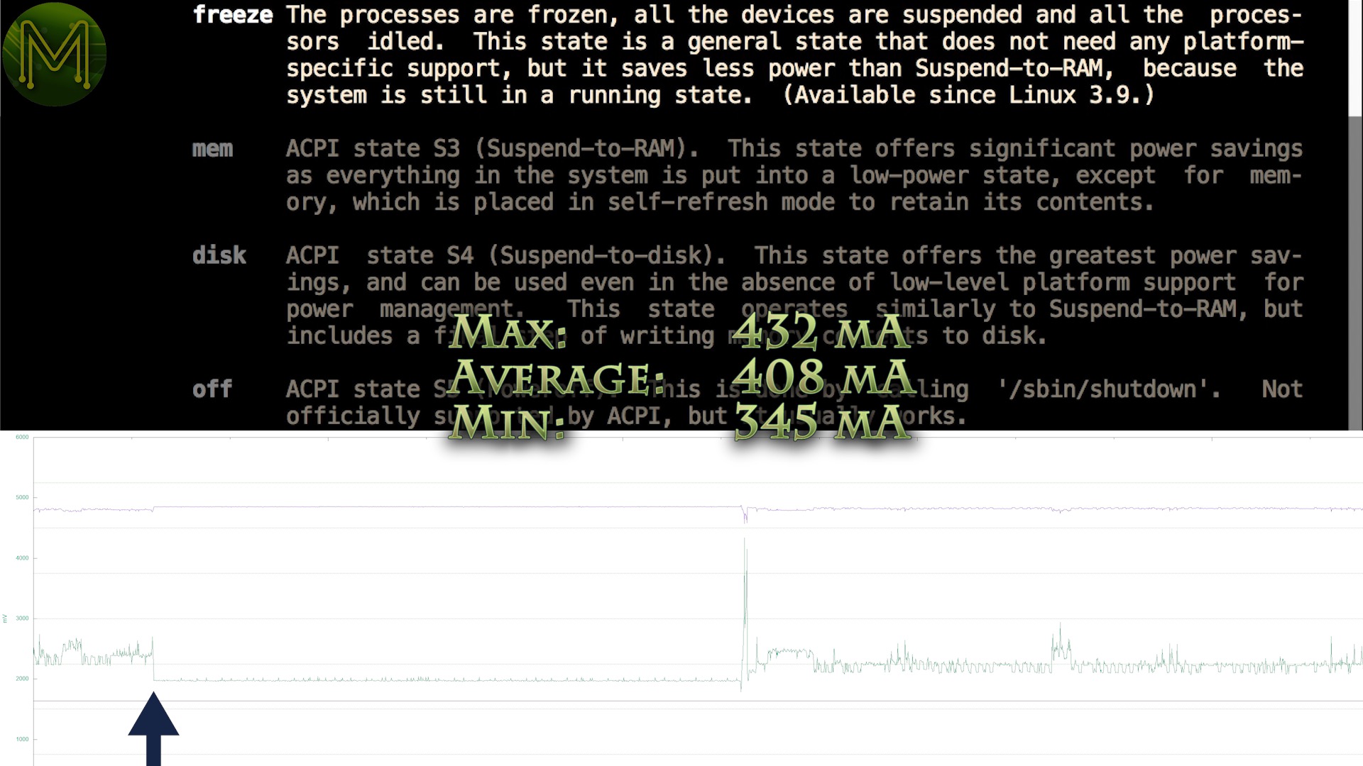
- Max: 432 mA
- Average: 408 mA
- Min: 345 mA
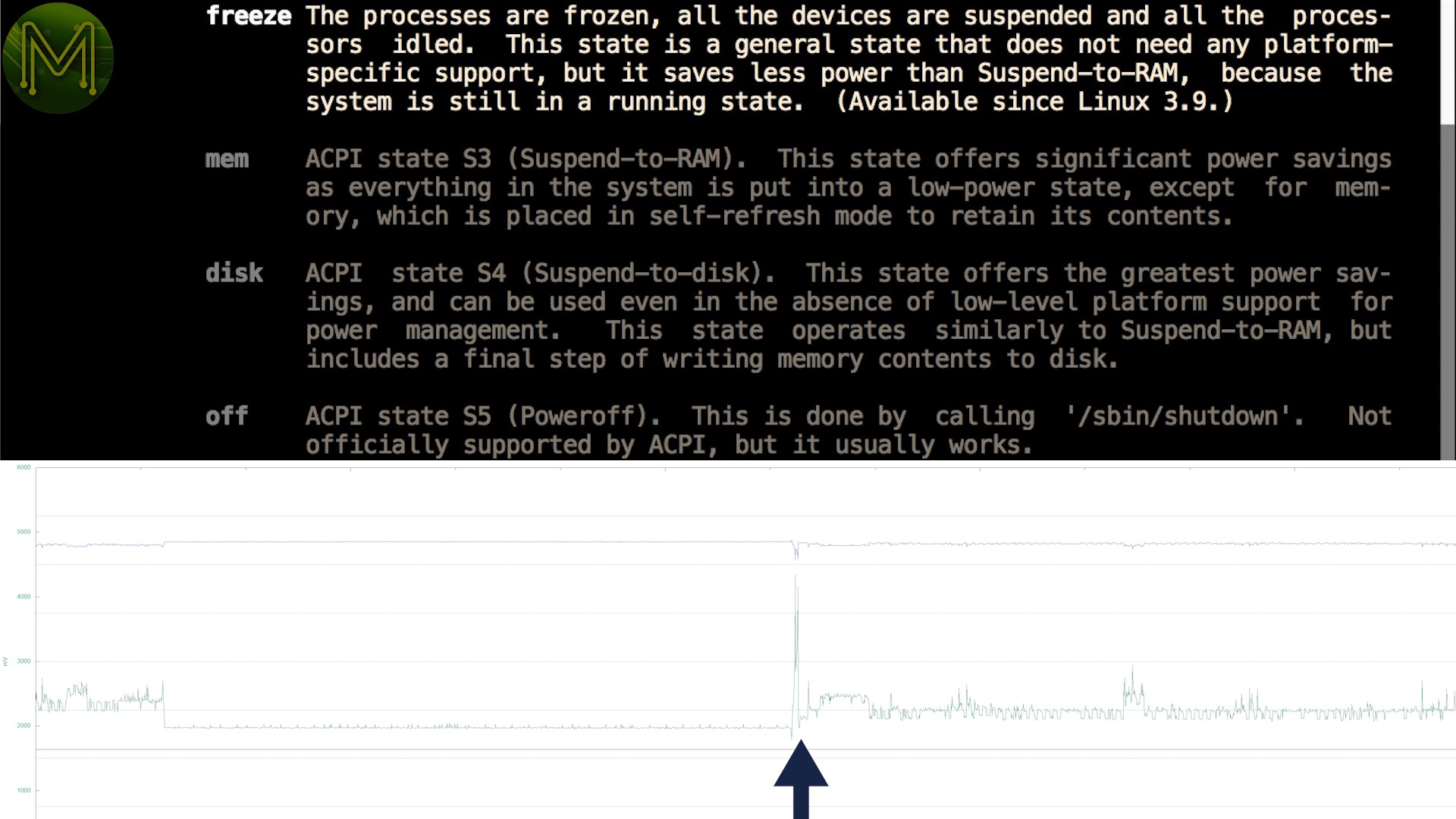
When the SBC woke from freeze mode, there was a sudden current surge of 1.2A lasting around 0.8 seconds. This is to be expected as processes and devices start back up again and something to bear in mind when using this mode.
Mem mode is essentially the same, but also suspends to RAM, giving you further reduction in power consumption. However, this mode never worked on the M4, for whatever reason.
Then there’s “off”, which speaks for itself really. As I mentioned before my power logger couldn’t measure down below 100uA, but it does indeed work well. Of course starting back up again from the off state saw the board hit a peak current draw of 1.6A with an average of 715mA. This all lasted around 20.3 seconds and then settled down into it’s idle current of around 550mA.
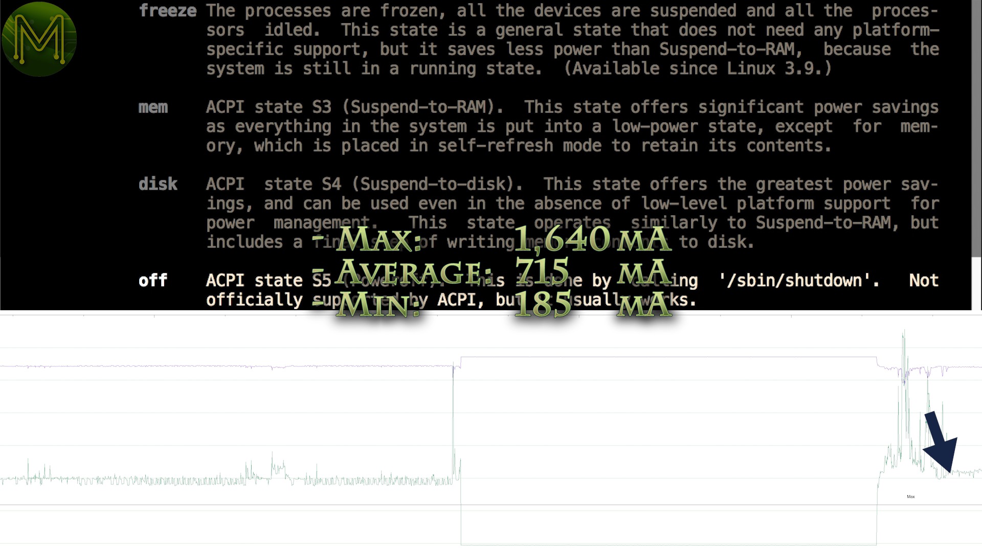
- Max: 1,640 mA
- Average: 715 mA
- Min: 185 mA
So, enough of mucking around with power. What about GPIOs? What works and what doesn’t? The O/S image comes with the wiringPi tools pre installed and configured.

There’s 6 I2C buses visible from the SoC with a bunch of devices visible on each of them. Of course, the last bus is the HDMI port which always hangs because of the Elgato HDMI recorder I use.

Pretty much all the I2C devices have kernel drivers. Most of them are related to power management, but there’s also USB Type-C control and MIPI-CSI ports.
You can query all the voltage levels pretty easily with a simple script.
There are four I2C buses available on GPIO pins. Two of them are at 3.3v logic levels, while the third one is running 1.8v levels and the fourth is on the MIPI-CSI connector, which runs at 1.8v.
So, can you actually access I2C? My handy dandy Lux sensor will be good enough for this.
Yup, looks OK to me.
BootingArmbian
OK, so now we’ve tried out the official FriendlyARM distro, let’s try out Armbian.
The reason for this is to check out the latest 5.0 series kernel, which has massive improvements for handling GPIOs.
Similar process to before, burn to SD, insert, power up.
It goes through it’s fiddly bits for a while and you get a plain login.
The first time you login to Armbian it prompts you to change the root password, setup a new account and then starts the desktop.
OK, so first up I should point out that currently the stock Armbian release doesn’t have the RKMPP acceleration built in by default, but you can add it in later.
To show you what difference this makes, here’s that same 4K demo video played back on stock Armbian. Not only is it not scaled properly, but it’s as slow as a wet week. With tonnes of frames dropped.
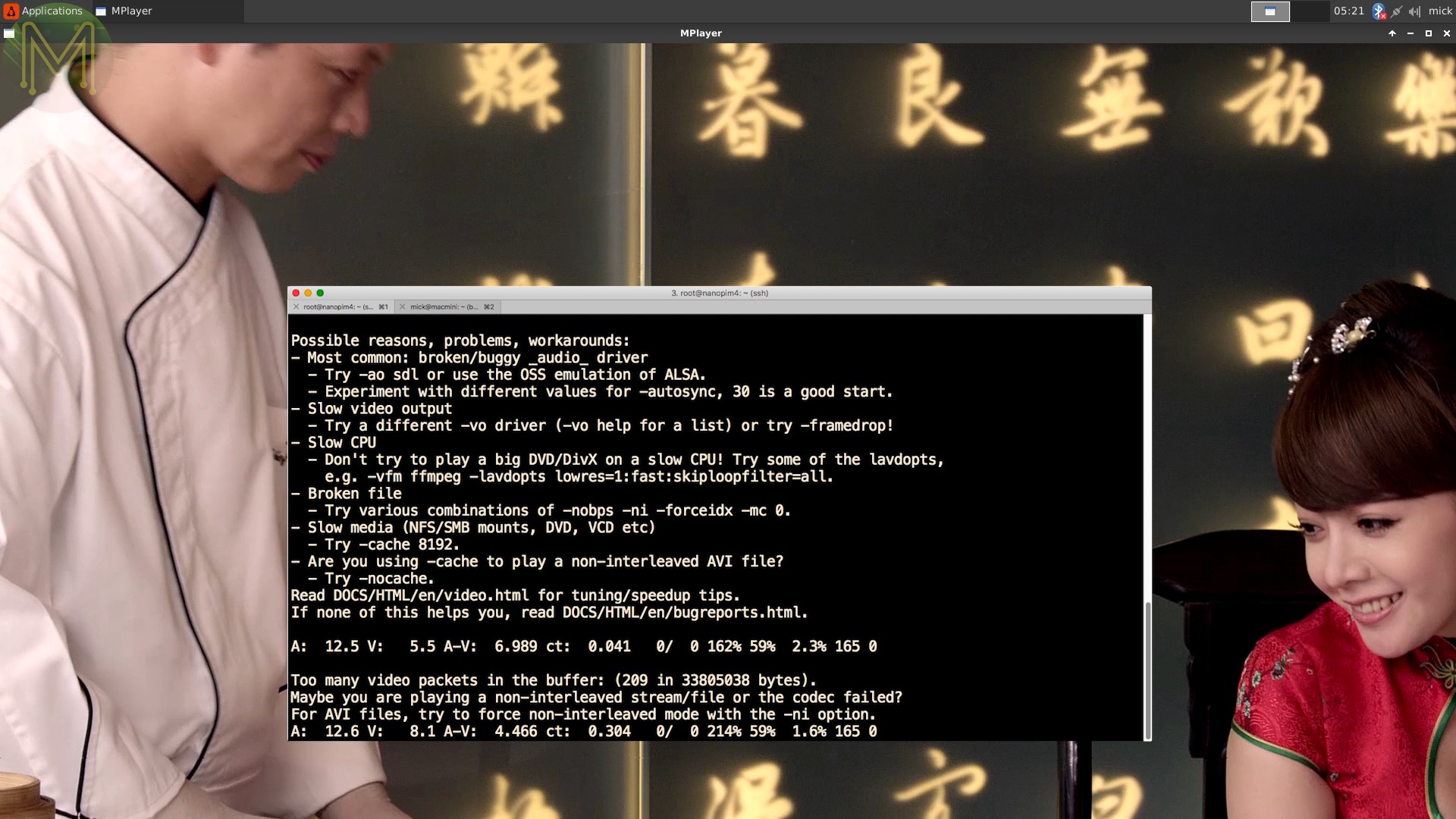
Scaling doesn’t make any difference either, which is to be expected.
And VLC sort of… oh OK.
So, if you head on over to the Armbian forums, you can pick up a script that fixes everything for you. Thanks to JMCC.
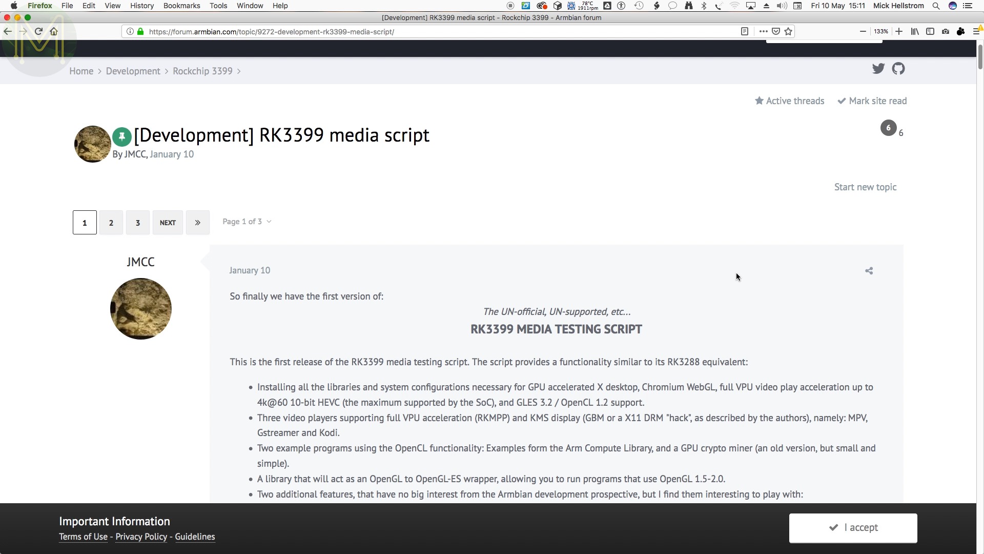
Just pull the tarball, extract and pick your options.
And don’t forget to disable the window manager compositing. If you saw my NanoPi NEO4 video, you’d see what happens if you don’t.
Then reboot.
However, after all those changes make sure to pick the right version of media player, otherwise you’ll get similar laggy results, but not only that it’ll often just hang and crash.
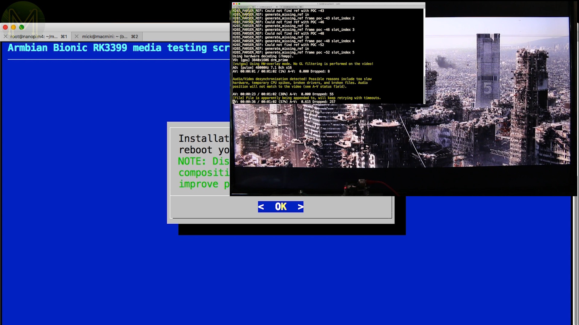
Using the correct RKMPP enabled media player, gives you what you want. Hmmm yum, dead chook… or is it duck? Hang on give me a minute. This is making me hungry….
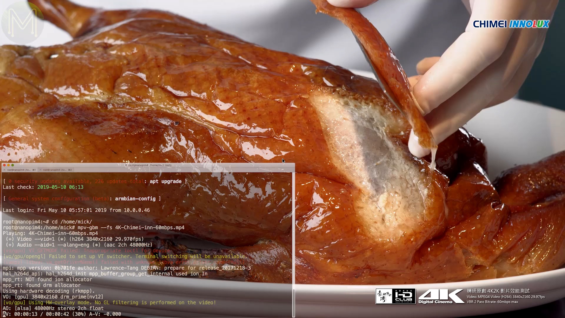
Allright. So where was I?
So make sure that you use an RKMPP enabled media player, for instance using an unmodified VLC, will give you this funky result.
Now I was interested to see just how much CPU playing a 4K video chews up. So making sure all CPUs are set to ondemand mode, and let it idle for a couple of minutes, I started up the 4K video playing in an endless loop.
So, the temperature rose from a 36 degree Celsius starting point to a maximum of 53. Still not a concern and bear in mind that this board had no fan on it.
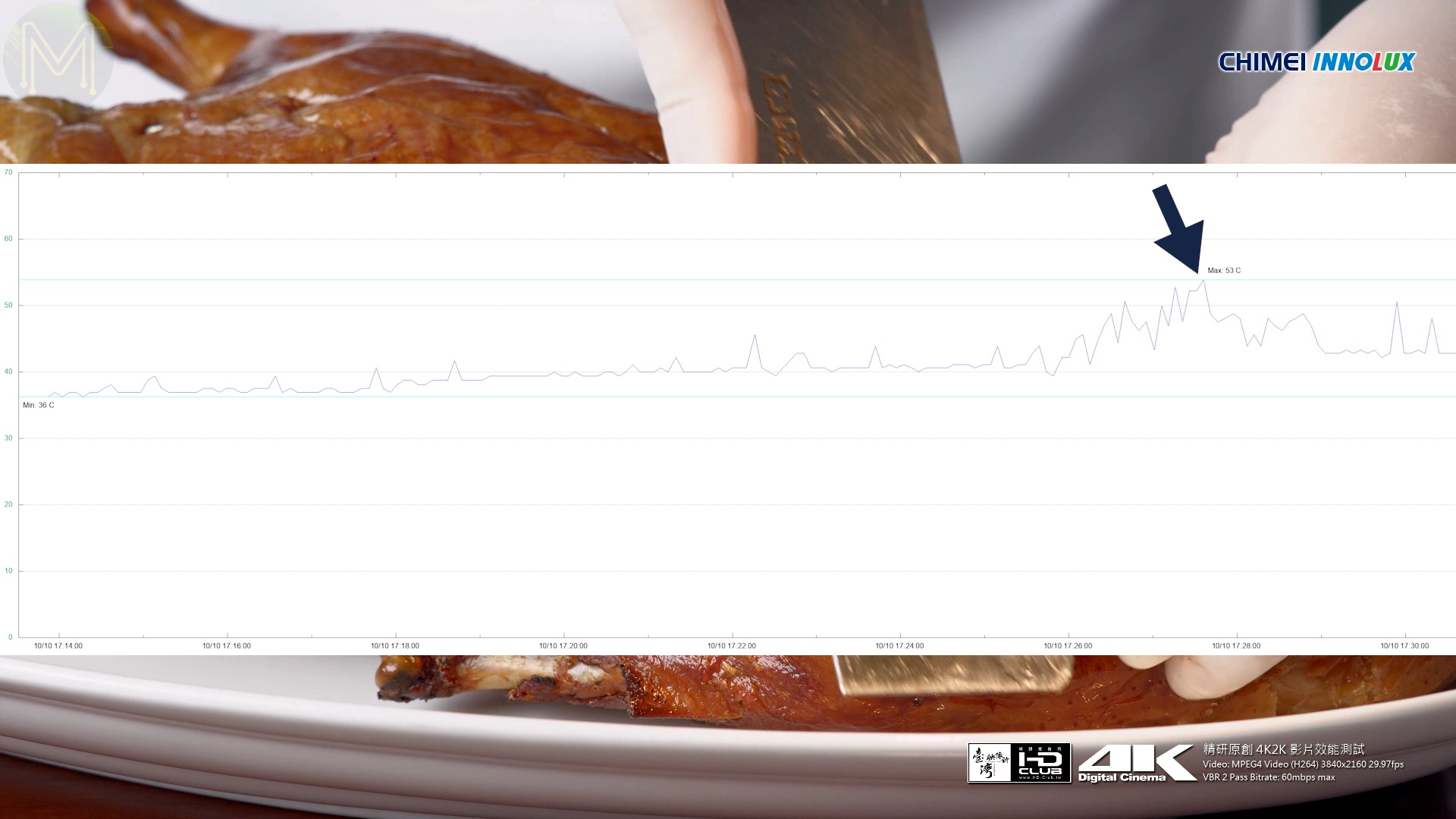
And the power consumption? Heck it just flat-lined at 550 mA, with the occasional blips on the radar.

Meanwhile the chook is still being massacared in the background.
All right, pretty decent result. So, before moving on to upgrading the kernel, let’s have a quick squiz at what else we have on Armbian.
All the PMIC voltage levels are accessible, of course. I2C is there with a bunch of I2C devices. And yeah, all the GPIOs work OK. No problem there.
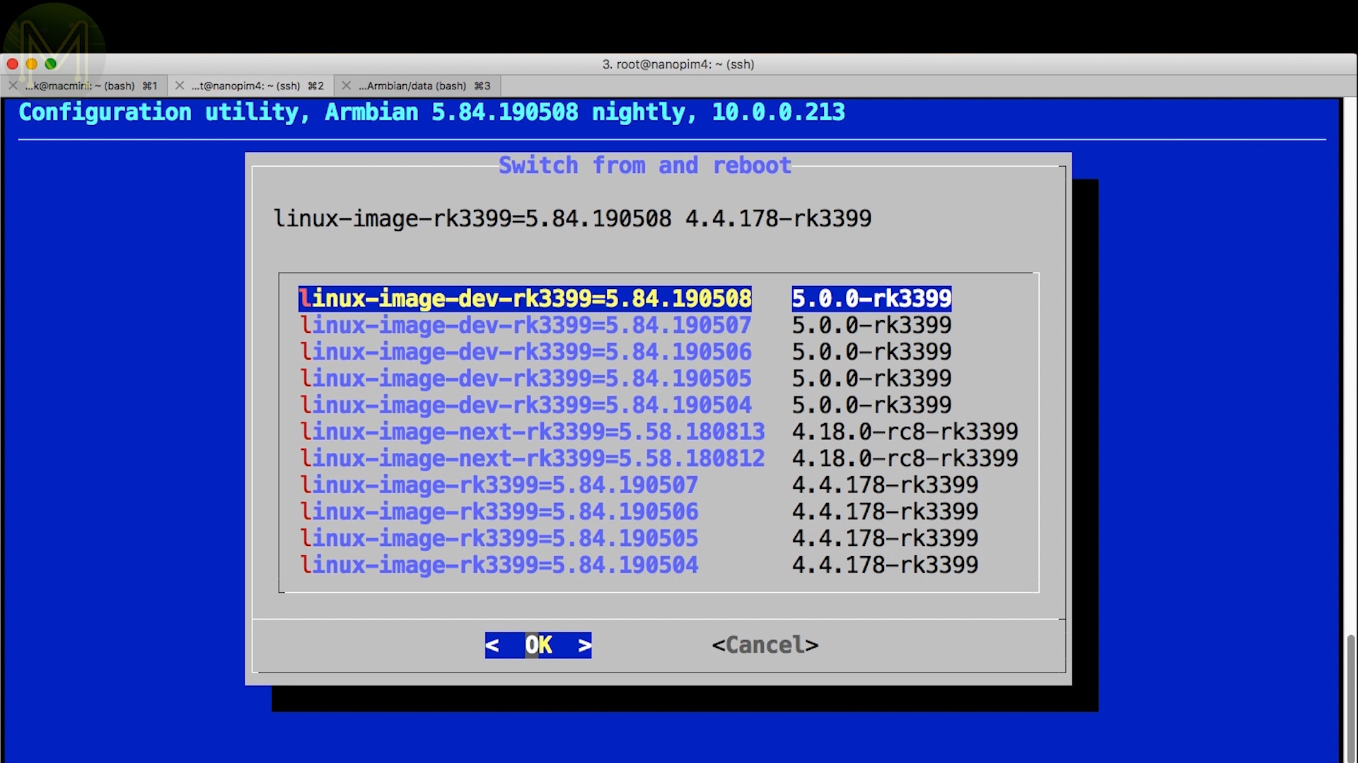
Allright, let’s upgrade the kernel. This is pretty easy just run armbian-config and first switch to nightly builds. Once it’s finished fluffing around, reboot. Then run armbian-config again to install the latest kernel.
Now that you have kernel 5 installed you can now use libgpio. There’s a number of tools provided in this package. gpiodetect will show up all the gpio chips available on the system. gpioinfo will show up all the deatils of each GPIO line. gpioget will make the GPIO an input and read the current state.
gpiomon will actively monitor and return the state of the GPIO.
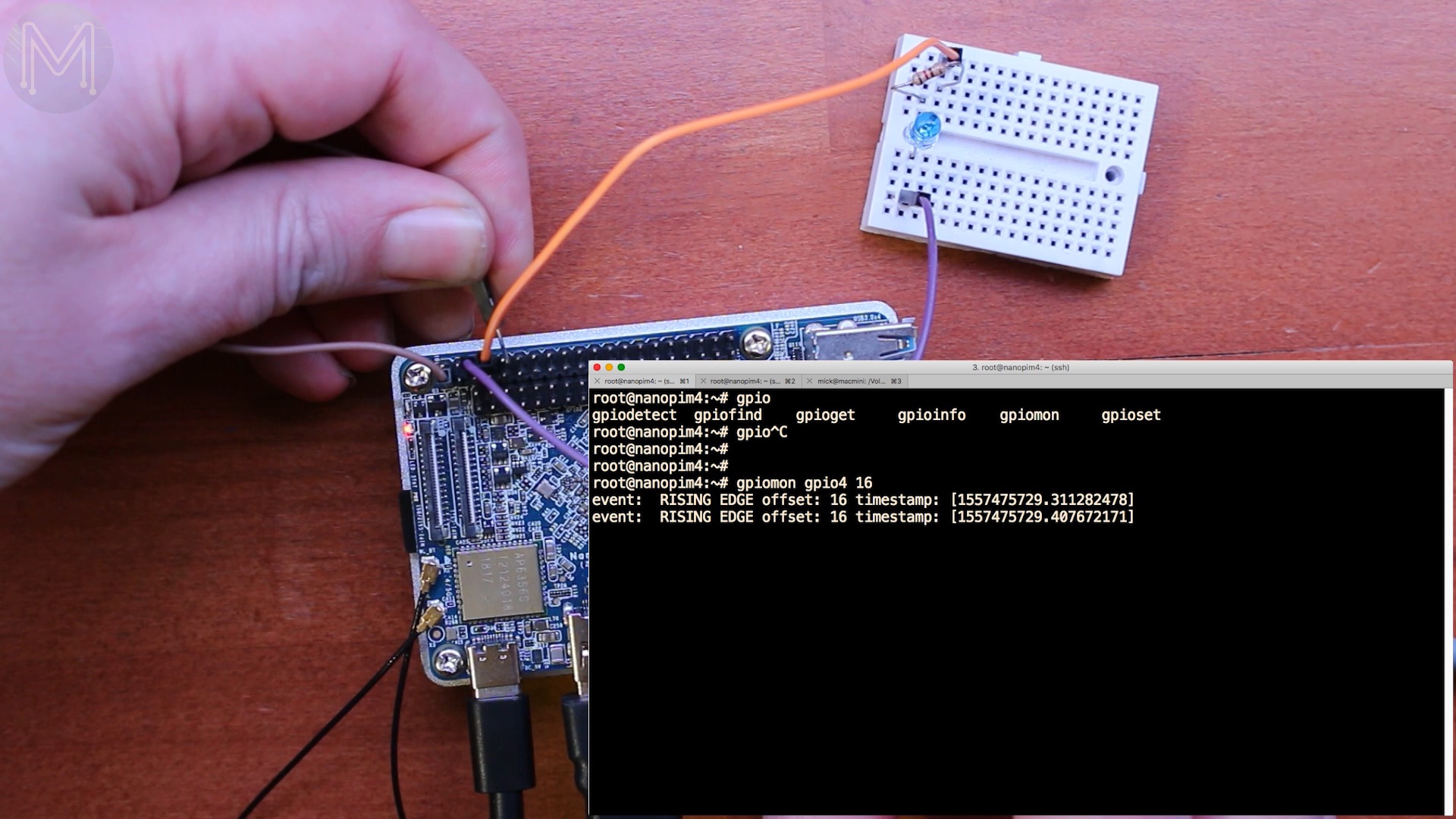
and gpioset will make the GPIO an output and you can set it to HIGH or LOW.

You can also make the GPIO lines active low, which essentially inverts the GPIO.
While I was testing out GPIO inputs I noticed something weird. I was trying to pull up a GPIO pin by attaching one end of a jumper to 3.3v. It sort of worked, but then the board crashed and rebooted. Weird.
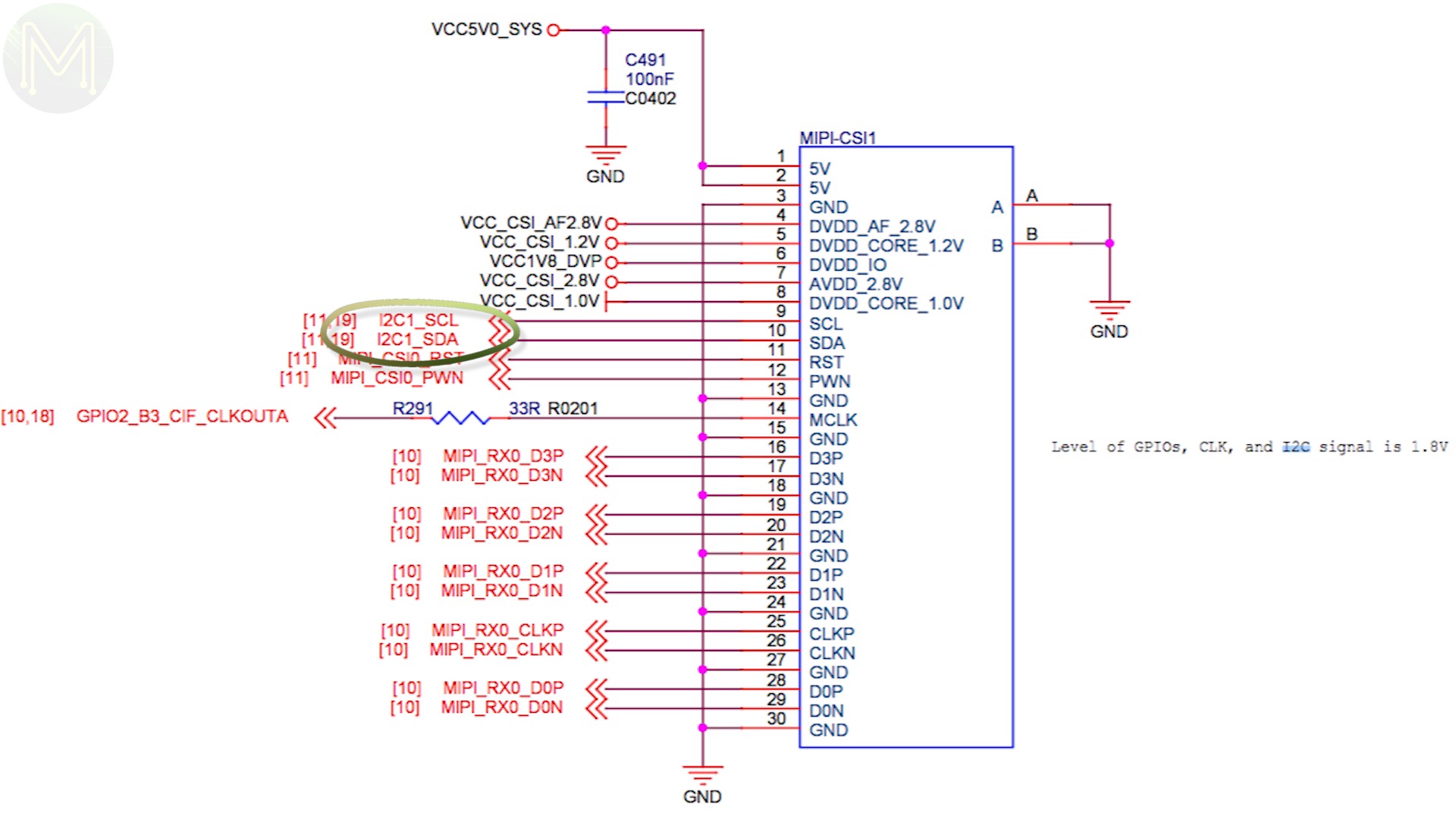
Looking at the schematic there seems to be a guff. The signals marked “3.0V signals” aren’t all correct.

The pin I was toggling, I2C3_SDA, feeds directly into the RK3399.
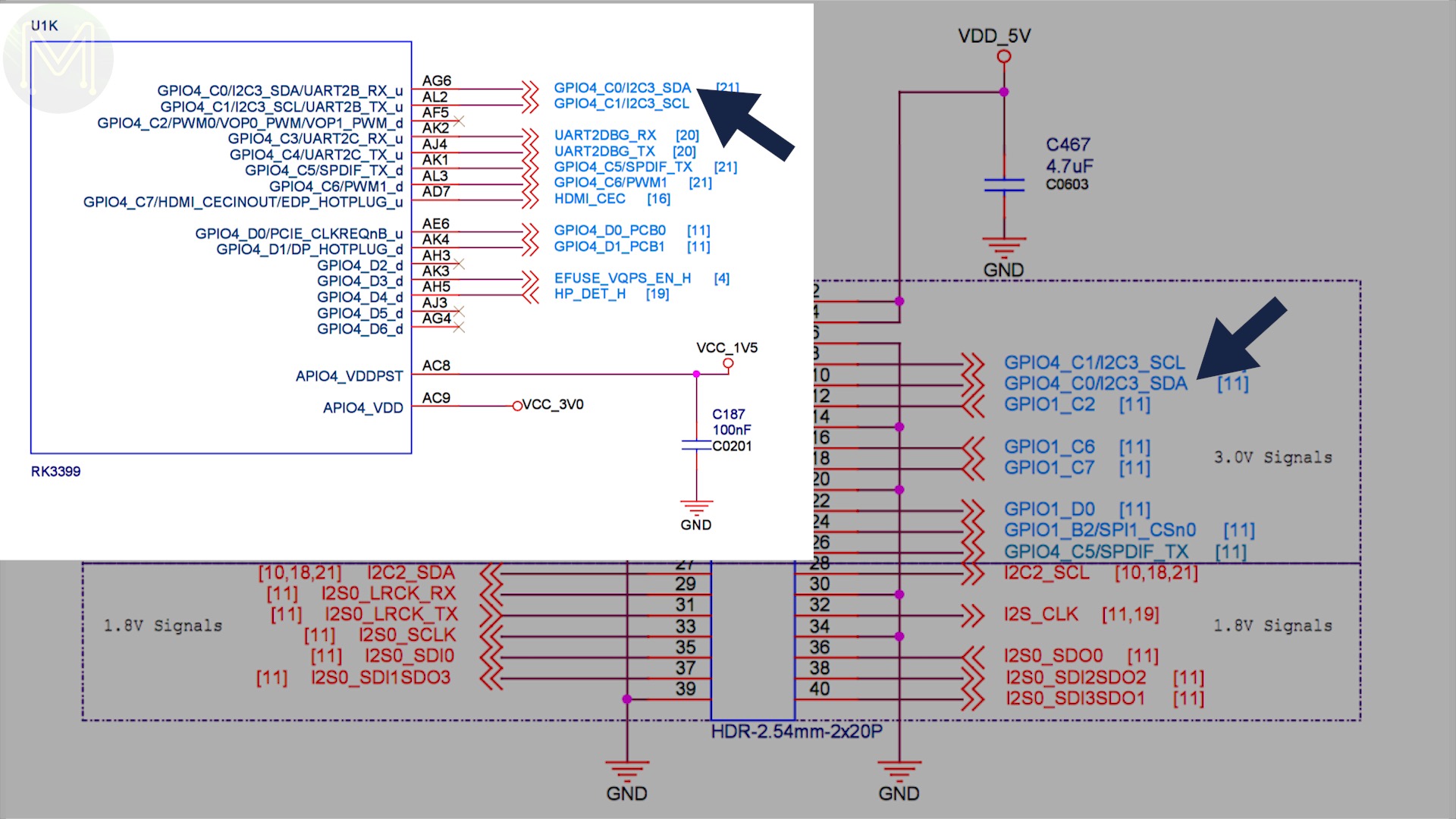
In fact a lot of the signals are incorrectly labeled.
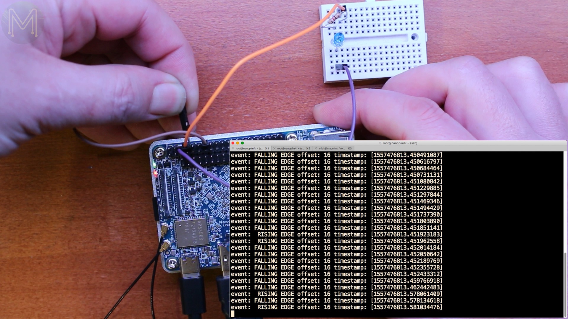
However, even after backfeeding 3.3v into the 1.8v line nothing was damaged. Phew.
So, since the GPIO lines all have pullup resistors, just pull the GPIO line down to ground and you’ll be OK.
Summary
So there you go! The NanoPi M4 is a pretty decent board where everything just works and I was having real trouble trying to find anything wrong with this board. The FriendlyARM guys are a good example of a company doing things right. All their products are now pretty mature and you can’t go wrong with any of their boards. So, if you’re looking for a decent alternative to the Raspberry Pi, check them out.
Now normally I run through a battery of Phoronix tests in my reviews, but I didn’t this time as I found there to be not much difference between the last 3 RK3399 based SBCs. However, if you’d like me to run a particular test on an SBC, or think I may have missed out something, then comment below.
So, I think that about wraps it up.