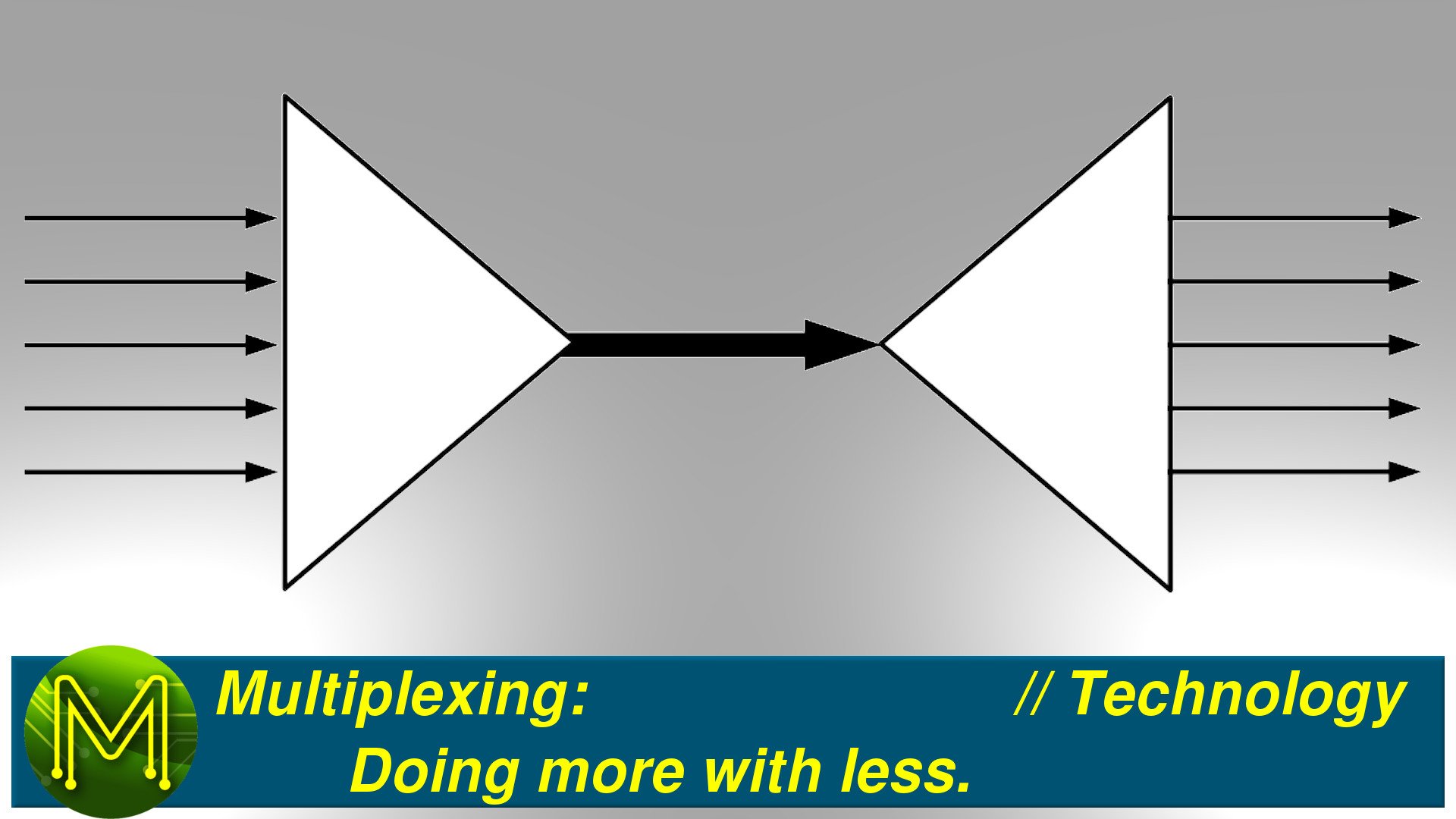
Multiplexing: Doing more with less. // Technology
Multiplexing was first used in the 1870s, but what is it and how is it used? What are the various types of multiplexing? What about keyboard matrices and Charlieplexing?
Purpose
Multiplexing, or MUXing, is a way of reducing the number of expensive wires, cables or RF transmitters by combining several signals over one medium.It was originally used in telegraphy in the 1870s to allow more than one person to communicate at a time, and was developed by George Squier in 1910 for the telephone carrier network.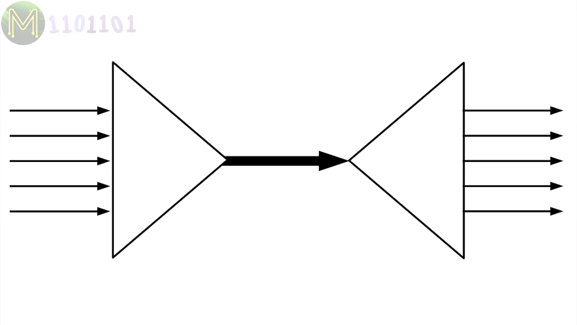

The opposite of MUXing is DEMUXing, which is a way of separating all the combined signals at the other end.
These days it is used in TV and radio stations, telephone networks, satellite communications, you are even using multiplexing to read this article and watch this video as you are sharing the Internet with billions of other users.
In electronics there are three common methods of employing multiplexing; Time, Frequency and Space.
- TDM - Time Division Multiplexing.
- FDM - Frequency Division Multiplexing.
- SDM - Space Division Multiplexing.
Time Division Multiplexing
In TDM, signals are combined in the time space by allocating a short, fixed timeslot where each source signal transmits a few bits or bytes.TDM is used primarily in digital communications, such as the old GSM network, but can also be seen in the old WAV audio format, which uses TDM to interleave it’s stereo channels much like a zipper.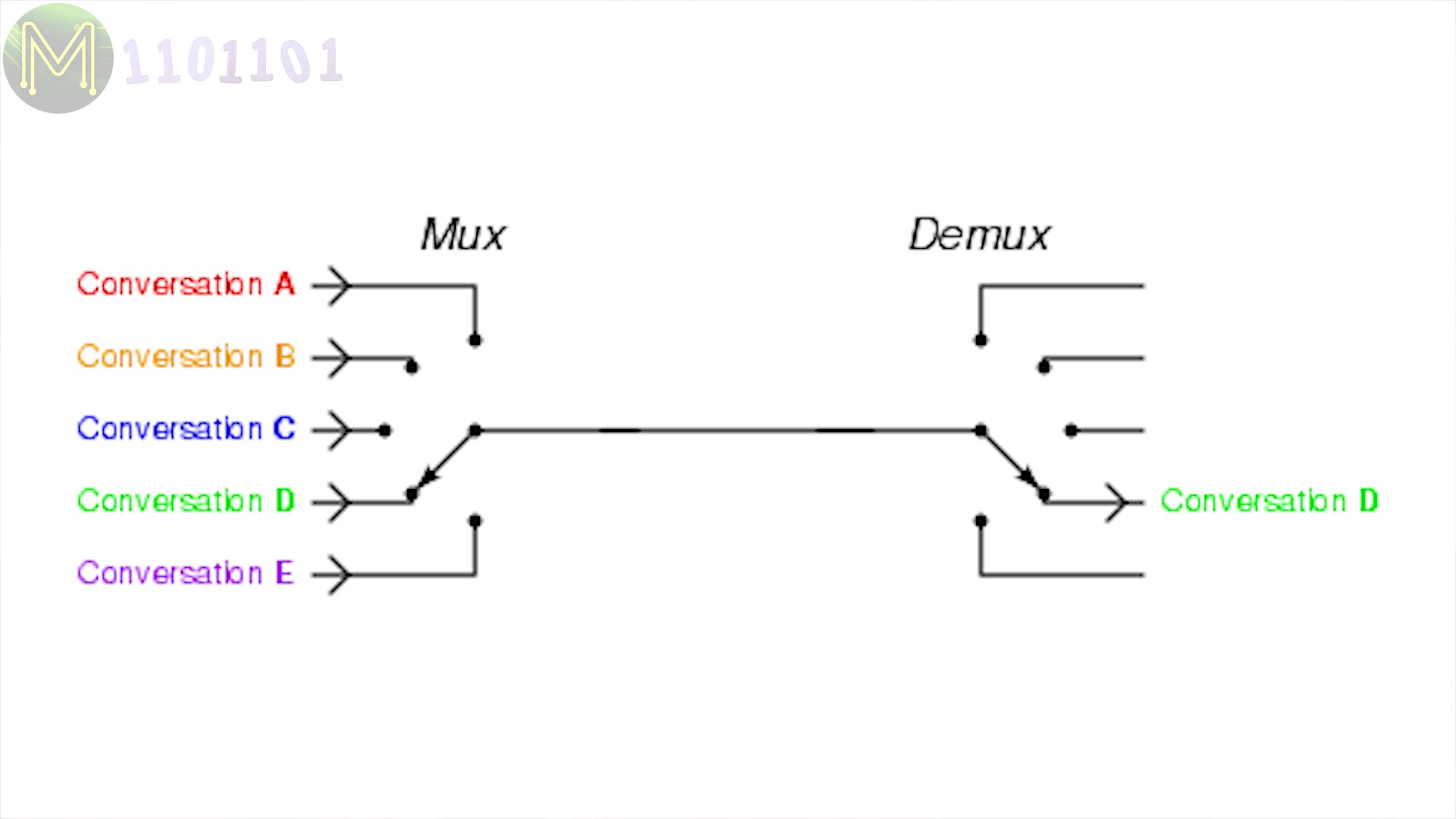

Frequency Division Multiplexing
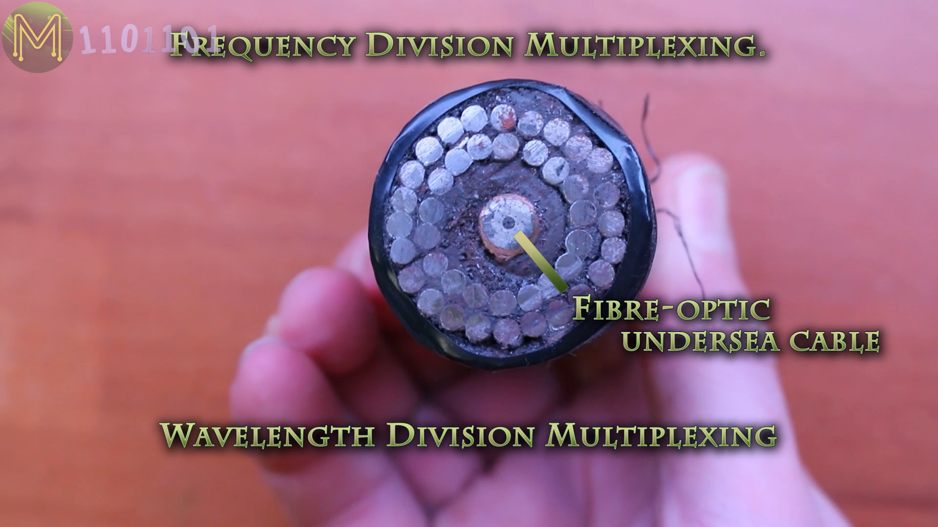
With FDM, signals are combined within the frequency space. Every TV and radio channel on the planet uses FDM as it shares the atmosphere when transmitting signals.FDM can also be used in cable television and can be referred to as WDM, Wavelength Division Multiplexing, when talking about fibre optic communications.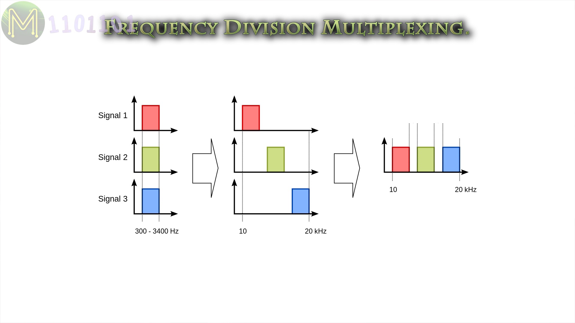
Space Division Multiplexing
With SDM, signals are combined within the space space…
Space, space?
Good examples of this is your landline telephone with it’s multi-pair wires, a humble I2C bus, an Ethernet switch with it’s many ports, mesh networks such as ZigBee, or your wireless Access Point, which uses phased array antennas to transmit several signals at the same time.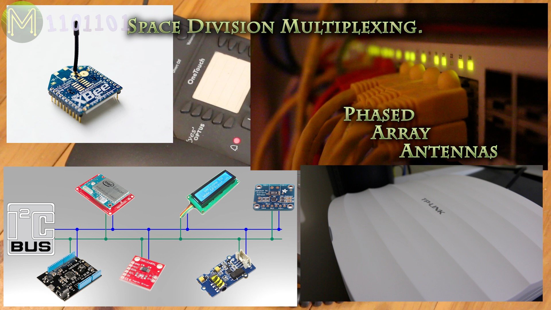
There’s also several other sub methods:
Polarization Division Multiplexing
PDM, which uses light polarization in fiber optics or orthogonal polarization in wireless to transmit two signals simultaneously. It is used primarily in fibre optics, microwave links and satellite communications.
Code Division Multiplexing
CDM, is something you have been using for many years and is seen in the humble mobile phone. Often also referred to as CDMA, it employs frequency hopping or DSSS to achieve multiplexing.
Orbital Angular Momentum Multiplexing
Finally, OAM, is a very recent technology that takes PDM further by using the orthagonal quantum states of light to multiplex signals. I won’t go into this here as it’s still only in research.
Uses
Whichever method you look at, they all have one common goal, which is to do more, with less.
When it comes to electronic circuits there are several semiconductors that use multiplexing.
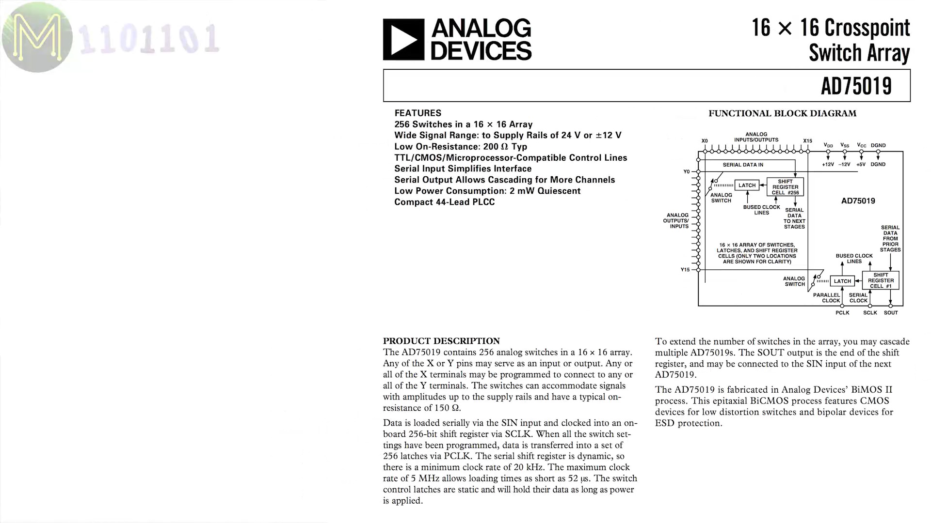
For example you’ll see ICs such as this Analog to Digital Converter, that has a single ADC on-board as they are expensive to produce, but can measure analog voltages from 16 channels.Or this 16 channel analog switch that you could use to connect to an expensive ADC or DAC.Or this IC that has 16 pins that can be connected to any of another set of 16 pins. Also known as a crossbar, or cross-point switch.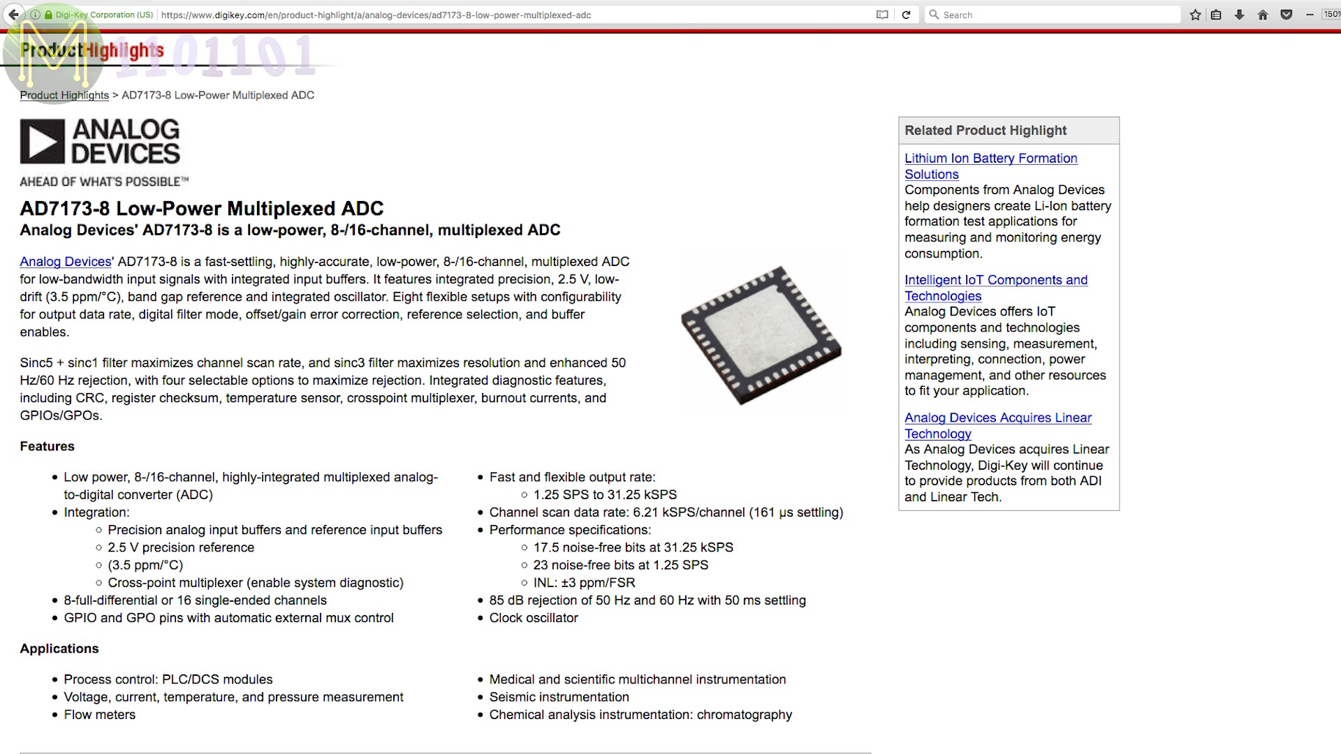

Keyboard multiplexing
Multiplexing is also used in keyboards.
Given a standard keyboard layout of around 104 keys, you would normally require 104 GPIO lines, which would result in a very large IC.
So, instead GPIOs are arranged in a matrix and keys placed at every point where X and Y meet.
This means that given 6 GPIOs you can scan 9 keys,or 11 GPIOs for 28 keys,or 24 GPIOs for 108 keys.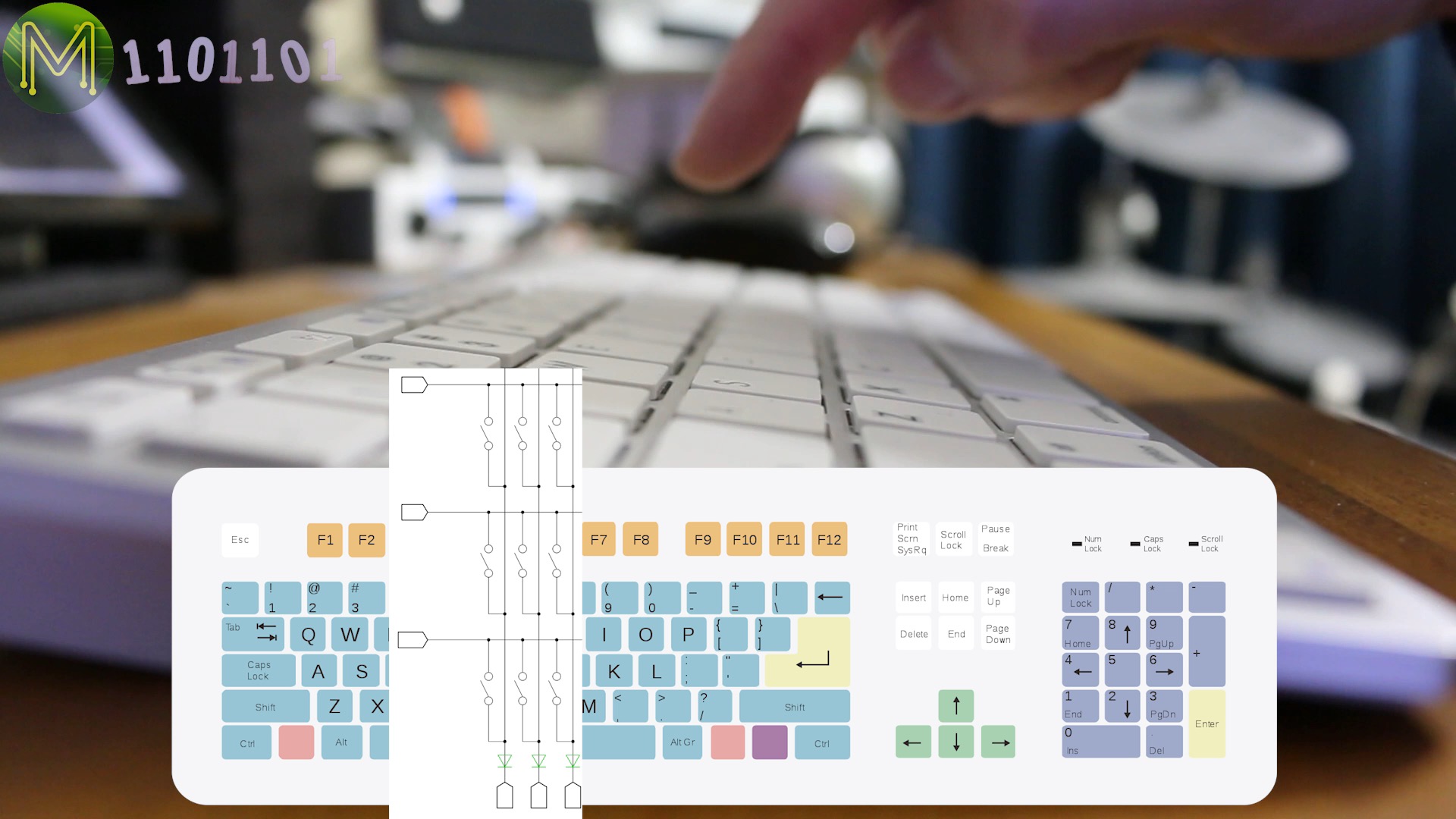

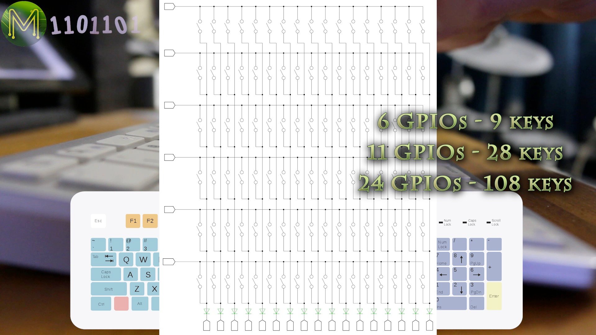
Keyboard ICs will scan across columns within the matrix at a certain rate to determine which key has been pressed.
Multiple keys can be pressed within each column,and keys pressed in other columns won’t affect the results of the current column as they’ll be in tri-state mode.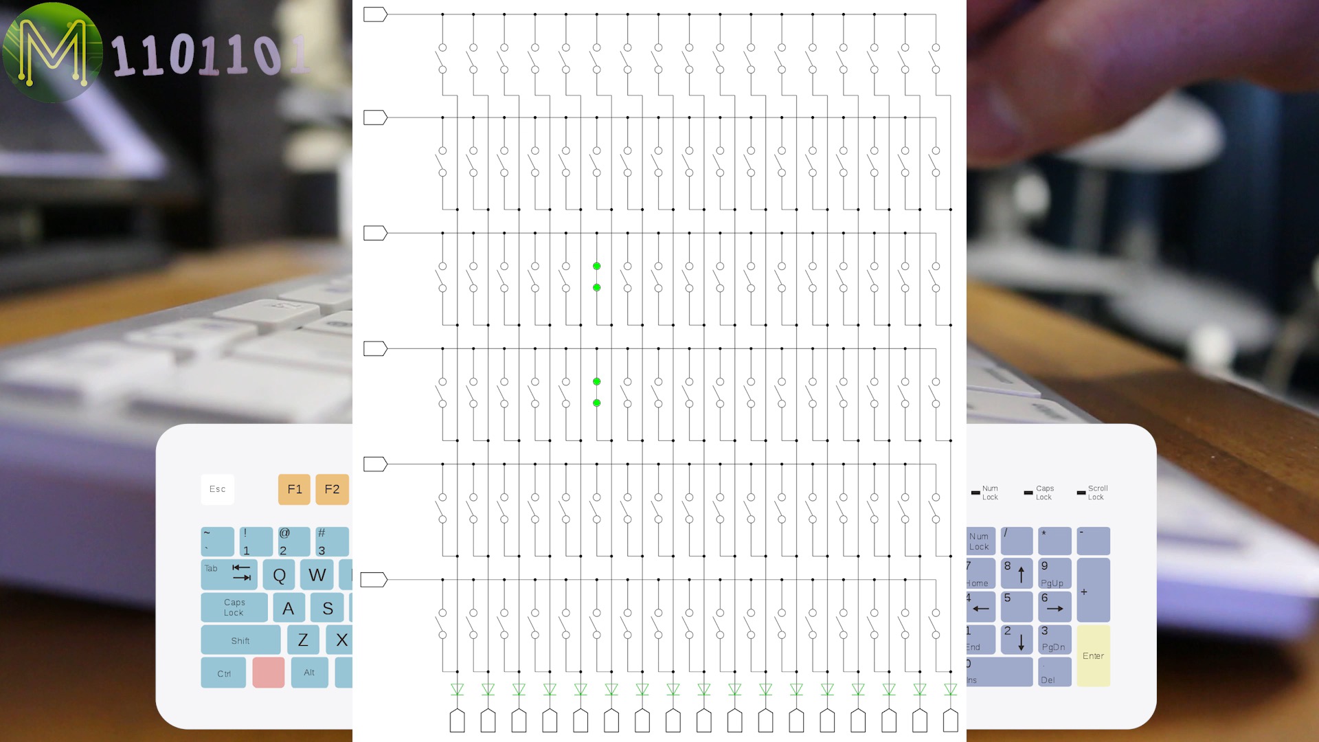

Resistor ladder
There’s also another form of keyboard multiplexing, where it relies on a resistor divider to determine which key or keys have been pressed.
Each resistor will be double the previous value, thereby ensuring any combination of keys can be pressed. This only requires one GPIO, but it has to be an analog input.
This works as a voltage divider where the buttons are tied to Vcc and the common line connected to the GPIO pin of your MCU, which is also tied to ground.
The incremental resistor values will effectively give you base-2 and since it’s a resistor ladder, the formula to calculate resistors in parallel is:
Rtotal = 1 / ( 1/R1 + 1/R2 + 1/R3 + 1/R4 ...)
Any switch not pressed will, of course, not be involved in the calculation. Once you have calculated the resistor value, then use the standard voltage divider formula to determine the output voltage to be expected. Here I use 5v as the voltage level.
5 * (Rtotal / ( Rtotal / 1000 ) )
Therefore:
| 1k | 2k | 4k | 8k | 16k | 32k | Calcohms | Voltage |
|---|---|---|---|---|---|---|---|
| 0 | 0 | 0 | 0 | 0 | 0 | 0 | 0 |
| 1 | 0 | 0 | 0 | 0 | 0 | 1000 | 2.50 |
| 0 | 1 | 0 | 0 | 0 | 0 | 2000 | 3.33 |
| 1 | 1 | 0 | 0 | 0 | 0 | 666 | 2.00 |
| 0 | 0 | 1 | 0 | 0 | 0 | 4000 | 4.00 |
| 1 | 0 | 1 | 0 | 0 | 0 | 800 | 2.22 |
| 0 | 1 | 1 | 0 | 0 | 0 | 1333 | 2.86 |
| 1 | 1 | 1 | 0 | 0 | 0 | 571 | 1.82 |
| 0 | 0 | 0 | 1 | 0 | 0 | 8000 | 4.44 |
| 1 | 0 | 0 | 1 | 0 | 0 | 888 | 2.35 |
| 0 | 1 | 0 | 1 | 0 | 0 | 1600 | 3.08 |
| 1 | 1 | 0 | 1 | 0 | 0 | 615 | 1.90 |
| 0 | 0 | 1 | 1 | 0 | 0 | 2666 | 3.64 |
| 1 | 0 | 1 | 1 | 0 | 0 | 727 | 2.11 |
| 0 | 1 | 1 | 1 | 0 | 0 | 1142 | 2.67 |
| 1 | 1 | 1 | 1 | 0 | 0 | 533 | 1.74 |
| 0 | 0 | 0 | 0 | 1 | 0 | 16000 | 4.71 |
| 1 | 0 | 0 | 0 | 1 | 0 | 941 | 2.42 |
| 0 | 1 | 0 | 0 | 1 | 0 | 1777 | 3.20 |
| 1 | 1 | 0 | 0 | 1 | 0 | 640 | 1.95 |
| 0 | 0 | 1 | 0 | 1 | 0 | 3200 | 3.81 |
| 1 | 0 | 1 | 0 | 1 | 0 | 761 | 2.16 |
| 0 | 1 | 1 | 0 | 1 | 0 | 1230 | 2.76 |
| 1 | 1 | 1 | 0 | 1 | 0 | 551 | 1.78 |
| 0 | 0 | 0 | 1 | 1 | 0 | 5333 | 4.21 |
| 1 | 0 | 0 | 1 | 1 | 0 | 842 | 2.29 |
| 0 | 1 | 0 | 1 | 1 | 0 | 1454 | 2.96 |
| 1 | 1 | 0 | 1 | 1 | 0 | 592 | 1.86 |
| 0 | 0 | 1 | 1 | 1 | 0 | 2285 | 3.48 |
| 1 | 0 | 1 | 1 | 1 | 0 | 695 | 2.05 |
| 0 | 1 | 1 | 1 | 1 | 0 | 1066 | 2.58 |
| 1 | 1 | 1 | 1 | 1 | 0 | 516 | 1.70 |
| 0 | 0 | 0 | 0 | 0 | 1 | 32000 | 4.85 |
If you work through each of the columns you’ll see that not one of the button press combinations are repeated. The downside is that you’ll need a fairly accurate DAC as you’ll expect to see a 0.01v resolution, which means you’ll need at least 500 steps.
5v / 0.01v = 500
500 steps means at least 9 bit resolution.
2 ^ 9 = 512
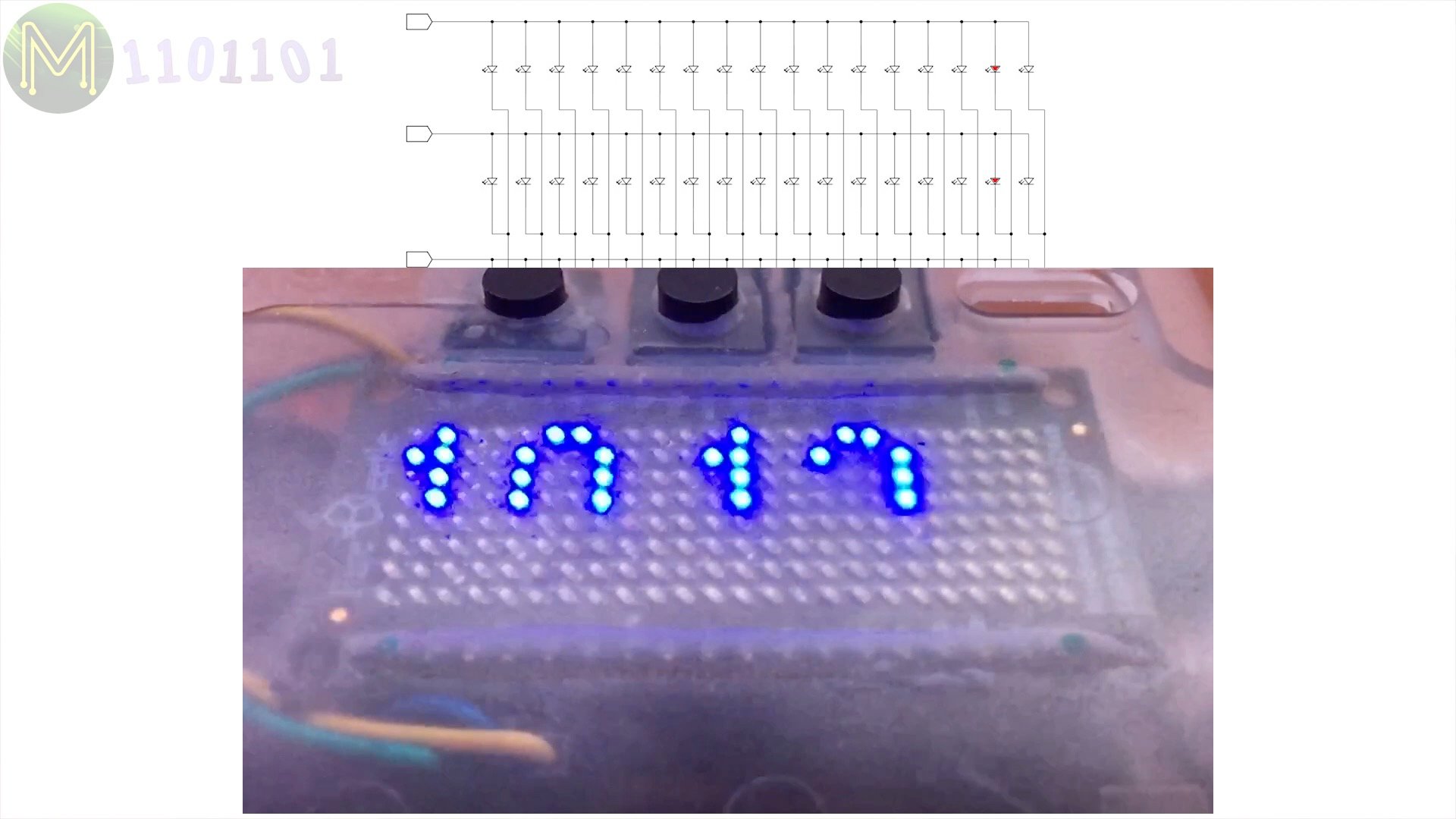
Display multiplexing
Matrix multiplexing is also used in displays with the switches replaced by LEDs at each point. A microcontroller will scan through the matrix lighting up a row at a time. This relies on Persistance of Vision in the human eye to fool us into thinking all LEDs are light up at the same time.
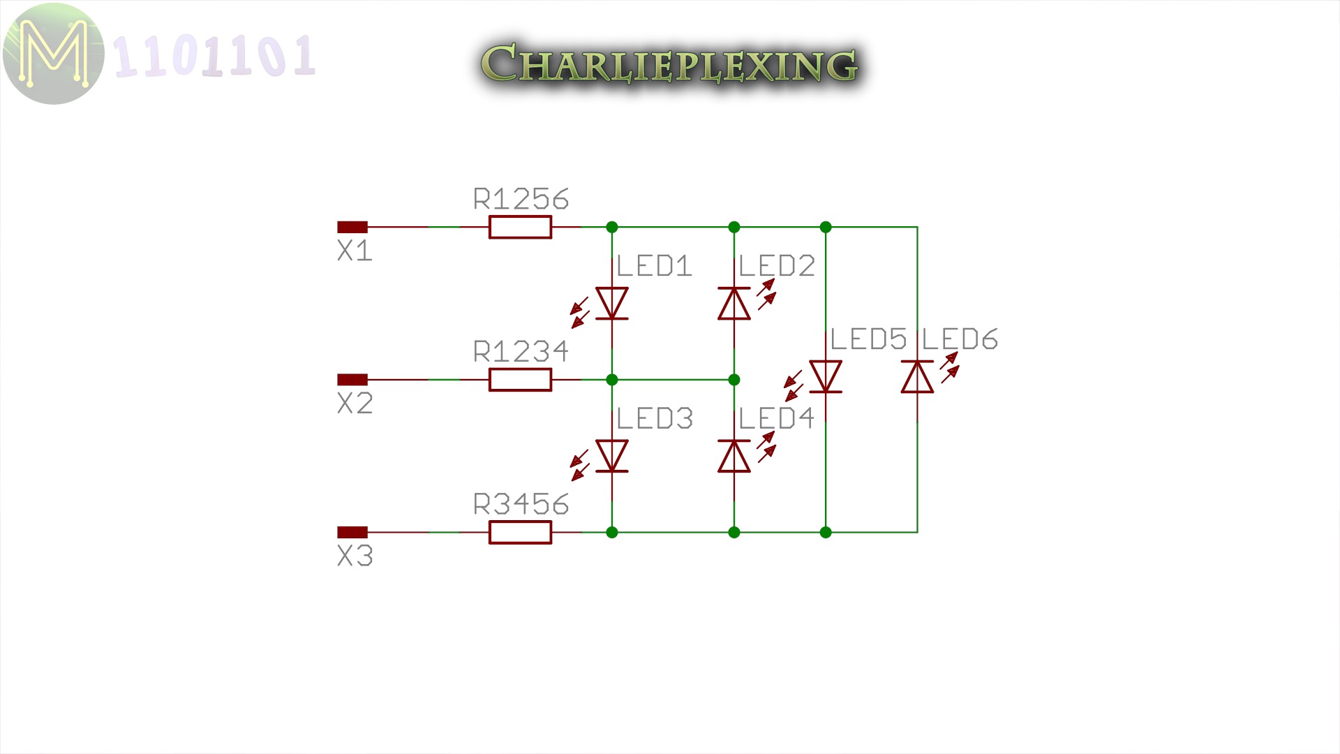
Charlieplexing
There is another form of multiplexing display called Charlieplexing.
Like keyboard multiplexing, Charlieplexing relies heavily on a GPIO pin’s ability to drop into tri-state mode. That is: High, Low, or not connected.
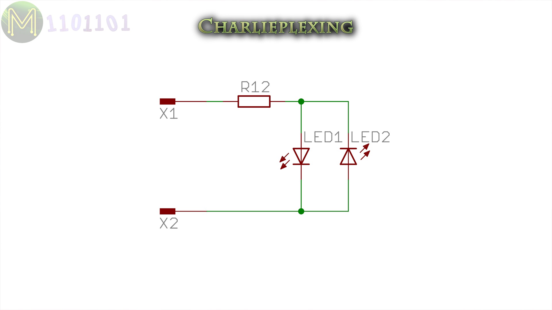
At it’s basic level Charlieplexing can be used to control 2 LEDs with only two GPIOs.
- Setting GPIO1 to high and GPIO2 to low will light up LED 1.
- Setting GPIO1 to low and GPIO2 to high will light up LED 2.
- Setting both GPIOs to tri-state mode will turn both LEDs off.

But there are a few disadvantages.
- There are no diagonal LEDs available, so you have to translate X and Y co-ordinates within software.
- LED brightness is much harder to control.
Much like dedicated keyboard controllers, you can also buy dedicated Charlieplexing ICs.
So as you can see multiplexing is actually very important within electronics, to allow sharing of minimal resources.
Copyright notice: Some of the images in this article have been taken from Wikipedia under the Creative Commons license.