
MickMake Mail #31: Pirl charger, LEDs & motor faders // News
This week’s mailbag I’m looking at the Pirl charger, motor sliders and 6,720 LEDs from a dumpster.
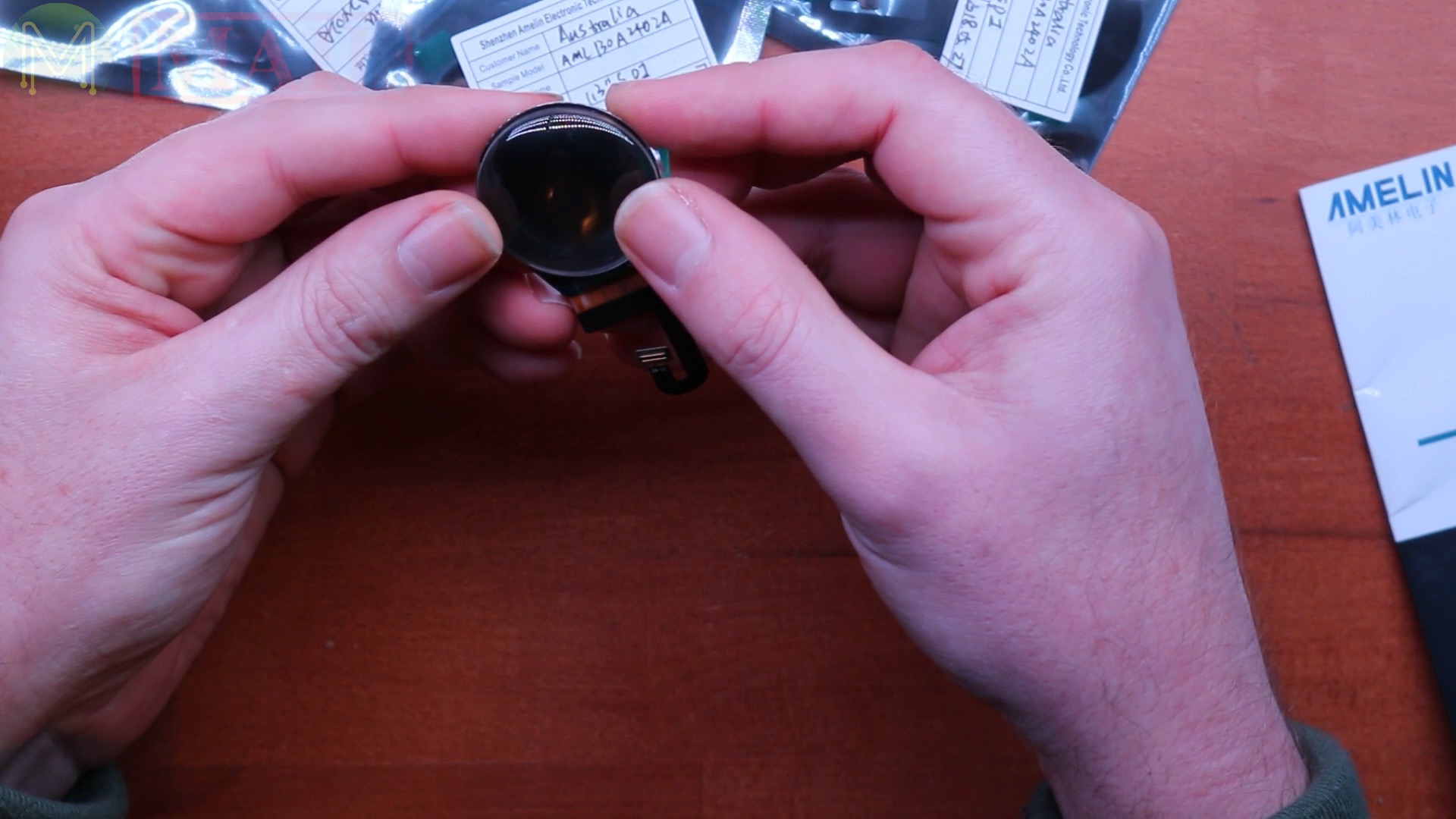
Round 1.3" TFT displays
So I ordered a bunch of LCD screens, so those sort of round circular ones you can get for watches. So these ones are based on the ST7789 interface, which is pretty common. The only issue though is that I have to find a little plug for that, which might be a little bit difficult since they’re surface mount devices.If you saw my previous mailbag, I’m trying to make an LED eyeball, essentially, so I’ve got these cabochons, which will extend the eyeball out.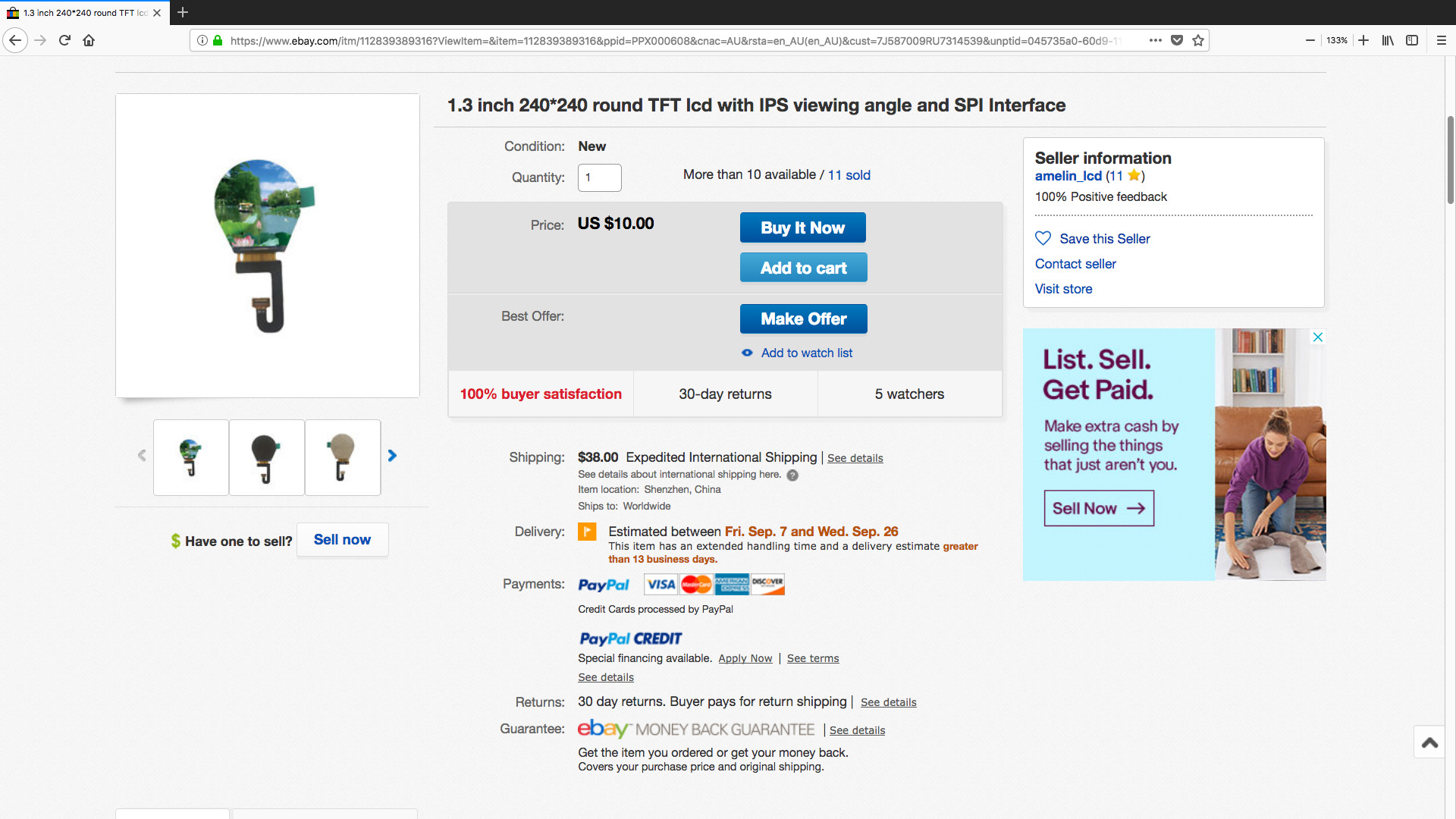
PiProjector Rev 2.0
Another JLCPCB order. Excellent!
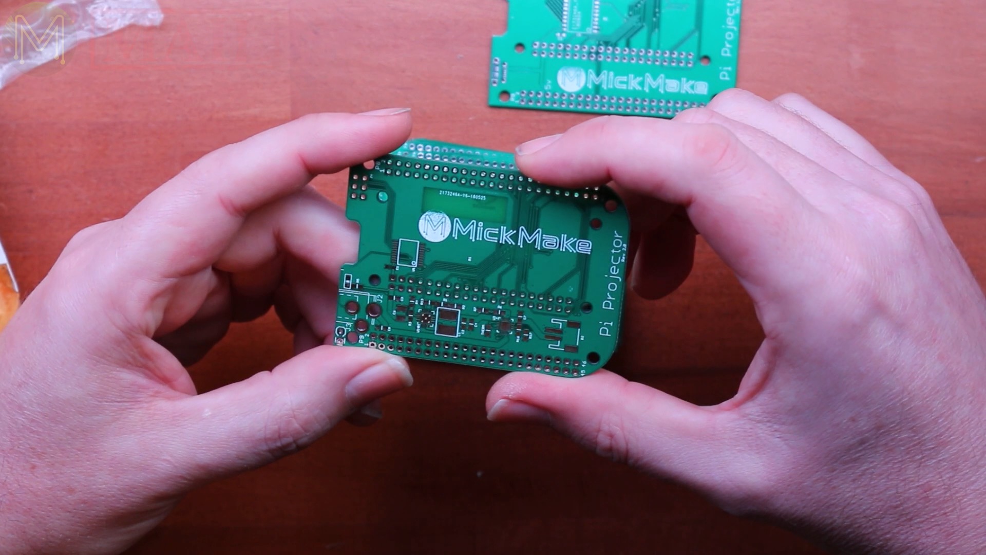
So these are actually the next revision of my Pi Projector. These are the 2.0 boards, which differs slightly from the previous major version.
For example, I’ve got a micro USB power connector and I’ve also placed an I2C based GPIO expander, which gives an additional eight GPIOs, which is quite good because all the GPIOs are taken up on the Raspberry Pi and was one of the issues that I had with it.
In Rev 2.0, I’ve added some substantial changes:

- For example, I’ve added in LiPo charging capabilities with a standard JST connector.
- I’ve switched over to using a standard DC jack instead micro USB.
- Also using four GPOs from the I2C expander, which can monitor things like whether you’ve got DC power coming in, the state of the LiPo, whether it’s charging, whether it’s not, and also the voltage levels as well, which is pretty good. So all I have to do is build them up and test them, make sure the design works, and of course I’ll still make available the rev 1 boards as a plain adapter board, which would be the cheaper version, and the other one, which will be the more expensive version, and I’ll sell them either as a kit with all the components supplied or a fully built and tested board.
The last batch of 30x of the Rev 1.1 boards have all been sold on Tindie. However, I’ve ordered another batch of 75 from JLCPCB and they should be ready in a couple of days.
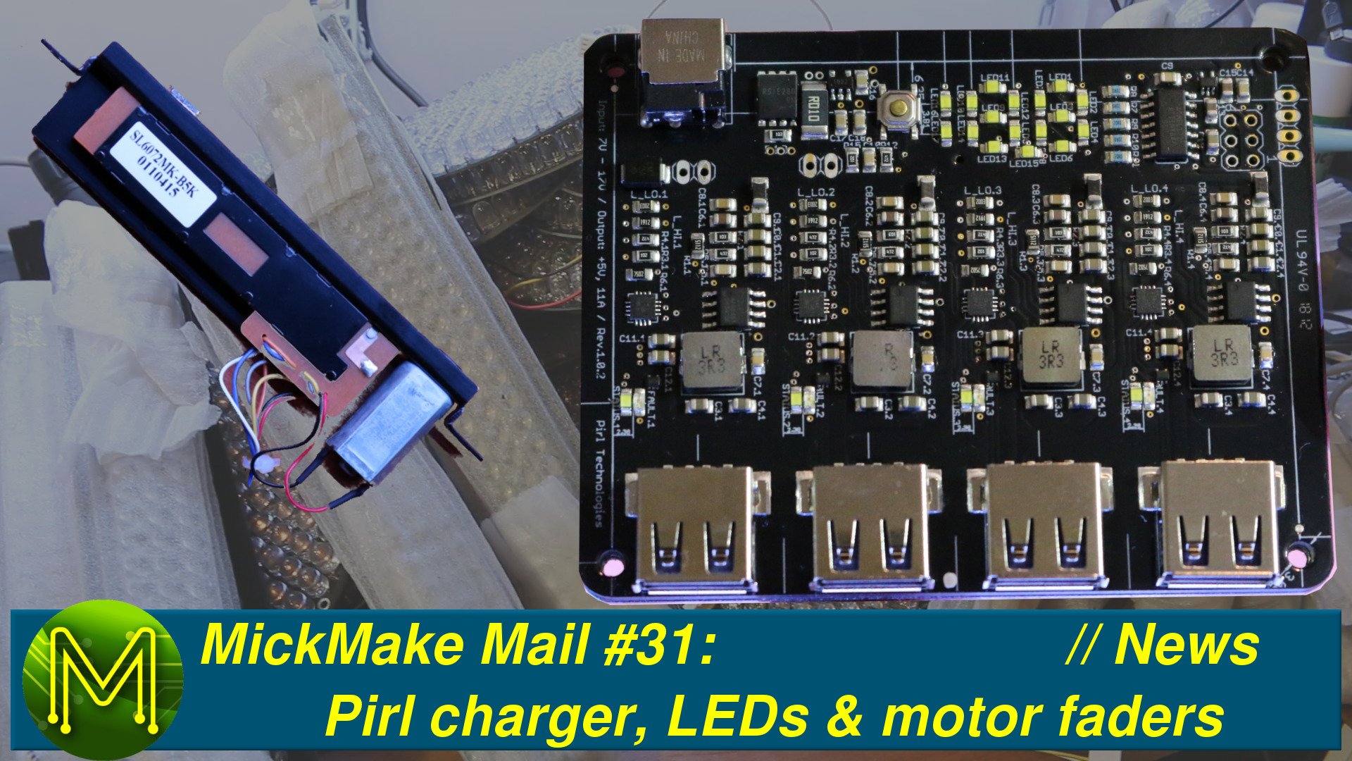
Pirl Charger
So onto the next one.
This is something that’s a Kickstarter, and I’ve got one of the early prototypes, which is the Pirl charger. I’ve seen a lot of YouTube video reviews on this, so the fellow’s doing some fairly decent marketing.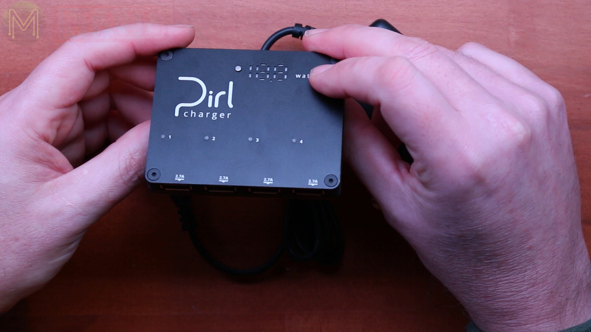
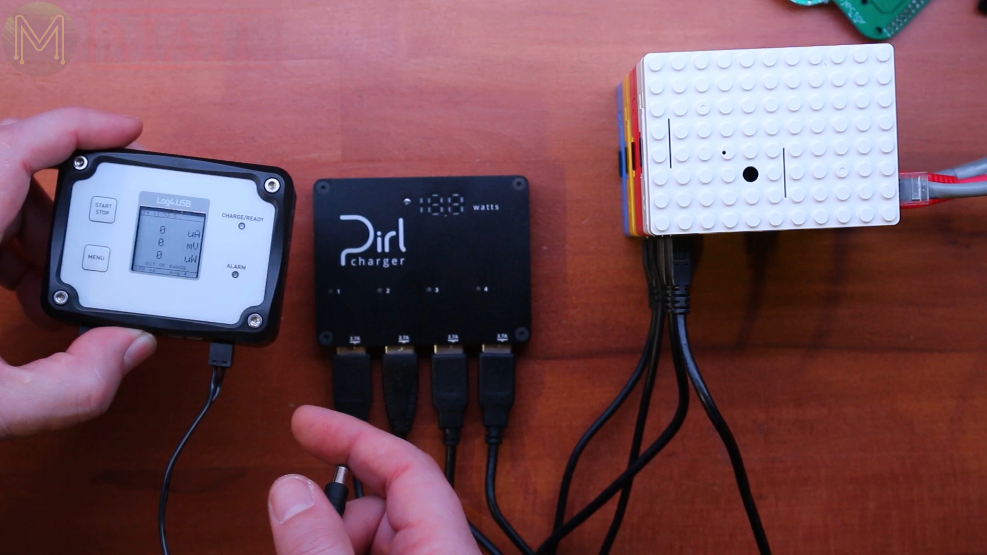
This is essentially a charger with four 2.7A charging ports, but the really good thing about this is it’s got four independent DC buck converters, which will charge the four ports independently. It also has a wide DC input voltage from 7 to 17V, so of course you can charge it from solar panel or whatever you want.
The nominal output voltage is 5.05V, but if it’s under heavy load then it will increase that to 5.2V. They also claim to have lots of protection, like over voltage, over current ,over temperature… over everything, and the whole unit runs off a 15V, 4A power pack, which is a pretty beefy little thing.
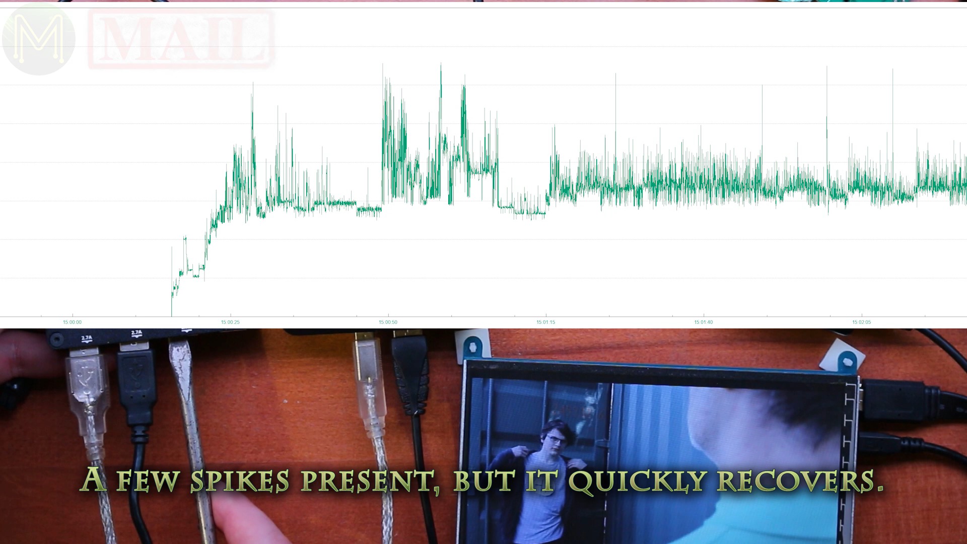
Okay, time to do a bit of testing. This is a fairly old Pi. A Pi 2 that I can play a video on without any problems.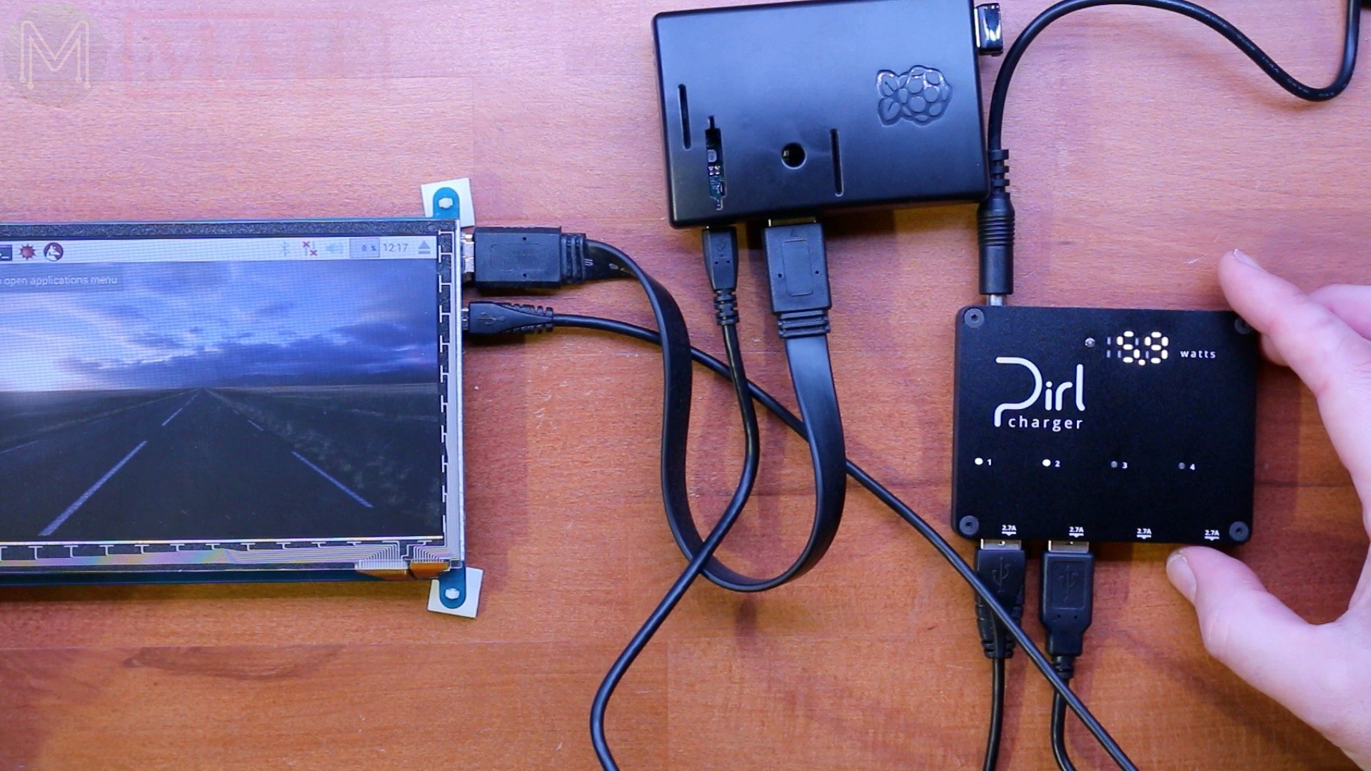
Of course, it works as expected, but it’s only drawing 5.7 watts, so let’s add a few more Pis on and see how much it draws. But before I do that, let’s check out the short circuit protection, which is supposed to be pretty good.
This is my handy short circuit protection tool. If the audio wasn’t so bad on the recording, you’d be able to hear a little buzz, and of course the pleasant sound of small voltage arcs, but you know what? It’s actually pretty stable. You can see the wattage increase every so often, but the Pi is completely unaffected.So let’s move onto some Pi 3 B+s and see if we can push the load up a little bit. So adding the extra four Pis increased the wattage consumption to around 8 to 8.3 watts. To increase the power consumption further ran the smallpt test from the Phoronix Test Suite, which should actually increase the current draw, and let’s see what the results are like.So the wattage increased to 22 watts, which is pretty decent, but the question is, is this actually accurate or not? Now there’s a way of testing this.So this time I added an inline power meter, which logs both voltage and current and will allow me to produce some nice pretty graphs.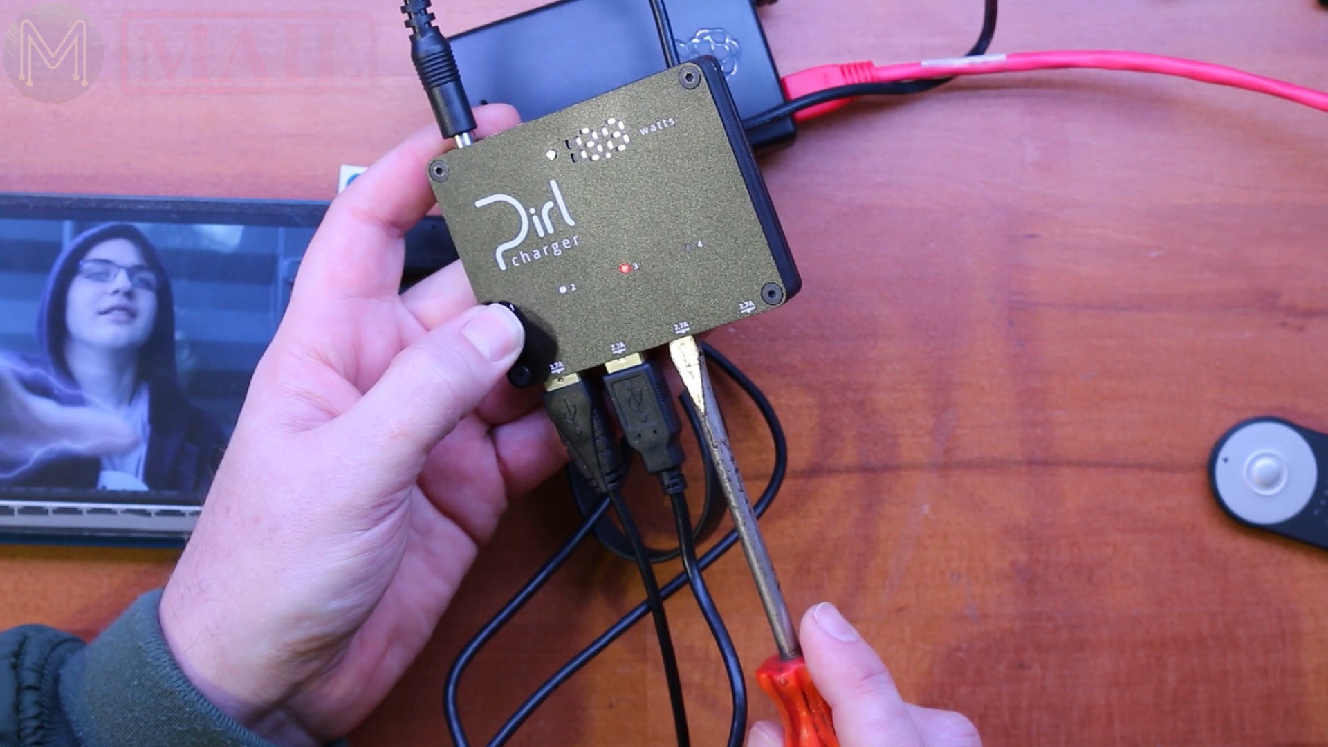
So I ran the smallpt test from the Phoronix Test Suite and I ended up seeing around 24 or 25 watts, which is around about right, because I think the internal circuitry on the Pirl charger will be using around about two to three watts. And well, the results, it’s a fairly consistent result.
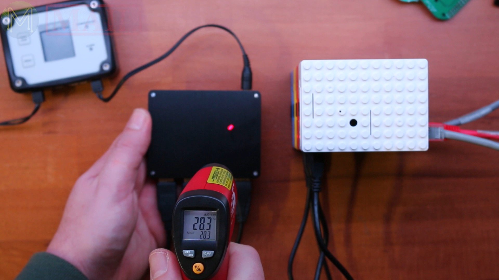
You can see the point where I started the Phoronix Test Suite which pushed the current draw right up, then dropped back right down again.Unfortunately, I don’t have a thermal camera with me, but I saw a maximum of around about 26.2 degrees Celsius on the front, and on the rear side roughly about 28 degrees Celsius, which is actually a pretty decent temperature considering I’m pulling 1.6 amps from 15 volts.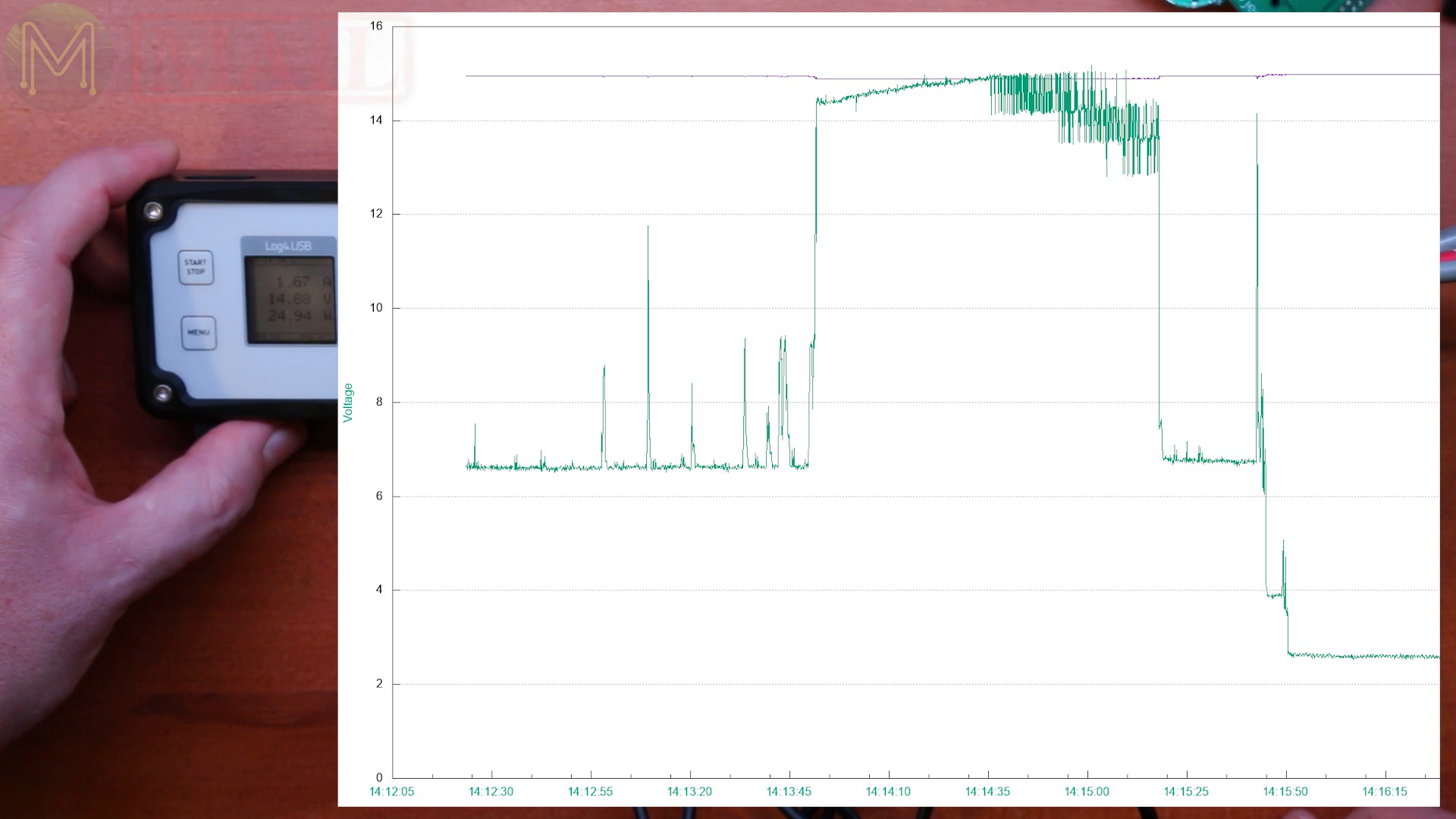
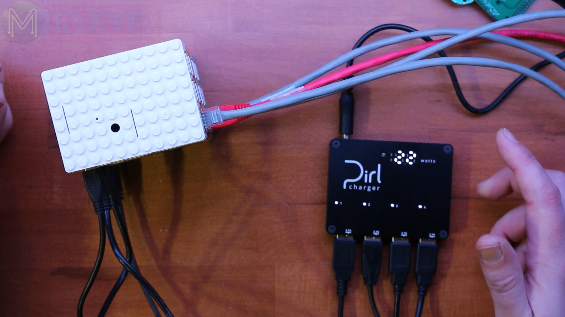
So going back to the single Pi, I connected up the power logger to the Pirl, and I wanted to see if there’s any impact on shorting out one of the DC buck converters.
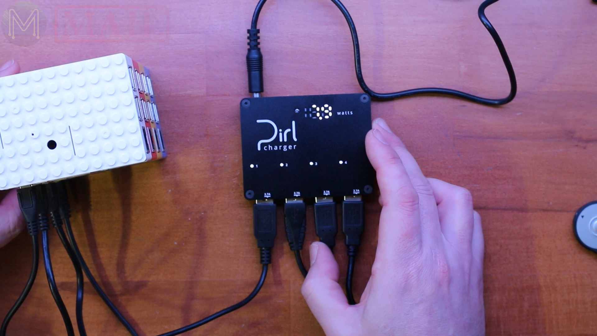
You can see the DC buck converter pulling a large amount of current for a very brief amount of time and then dropping back down again, so this is actually doing the job.This time I’ve connected the USB logger in series with the Pirl charger, so I’ll be able to see if any disruption on the other USB ports actually cause a disruption on other ports. I powered it all up and started playing a video.So I think enough mucking around with it. Let’s crack it open and see what it looks like on the inside. That’s a pretty neat little unit. Oh, yeah. It’s a 3-D printed case as well. As expected, there’s four individual DC buck converters. So the voltage looks like comes straight in from the DC jack, all the way into each of the DC buck converters. So that’s quite a nice little unit.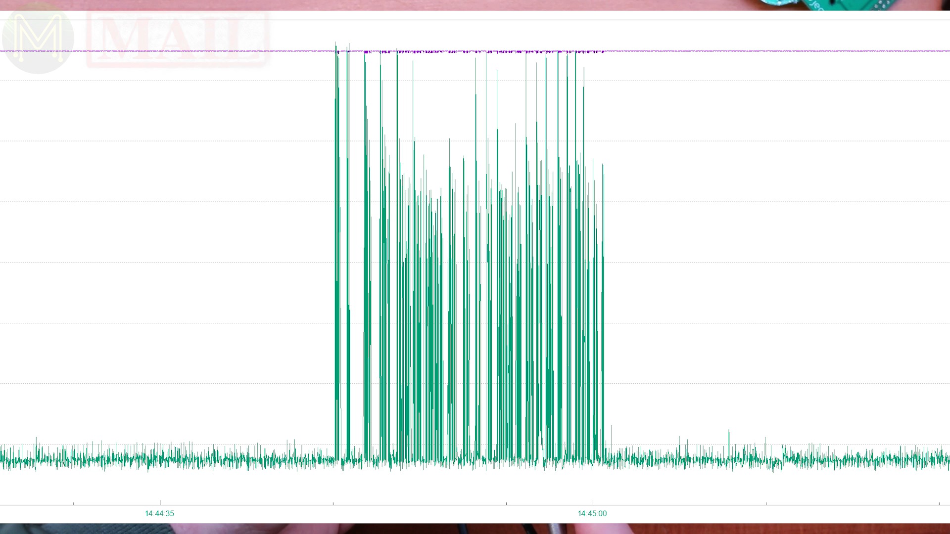

Dumpster Diving - Lots of LEDs
Okay. So my son went dumpster diving a while ago and picked up the a whole lot of these things. So these are RGB LED panels. The LEDs don’t have red, green, and blue inside each one, just individual red, individual green, and individual blue LEDs.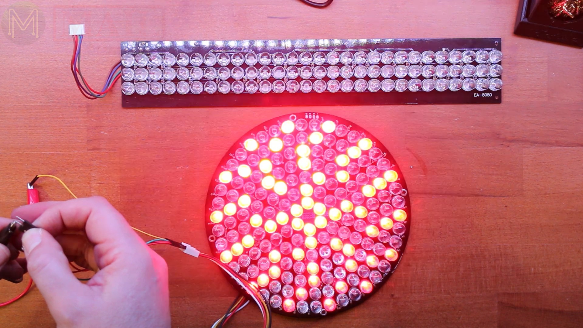
There’s straight panels and round panels. They were throwing out a lot of these things. They’re quite bright too. Each group of LEDs draw about 700mA and all of them powered on drawing about 1.3A. The circular ones are pretty much the same.
What actually makes this a really good dumpster dive is exactly how much I managed to get. If anyone can think of what to do with probably a couple thousand LEDs of red, green, and blue, just leave a comment down below and let me know. I just can’t think of anything at the moment to do with these. They’re pretty decent 12V LEDs.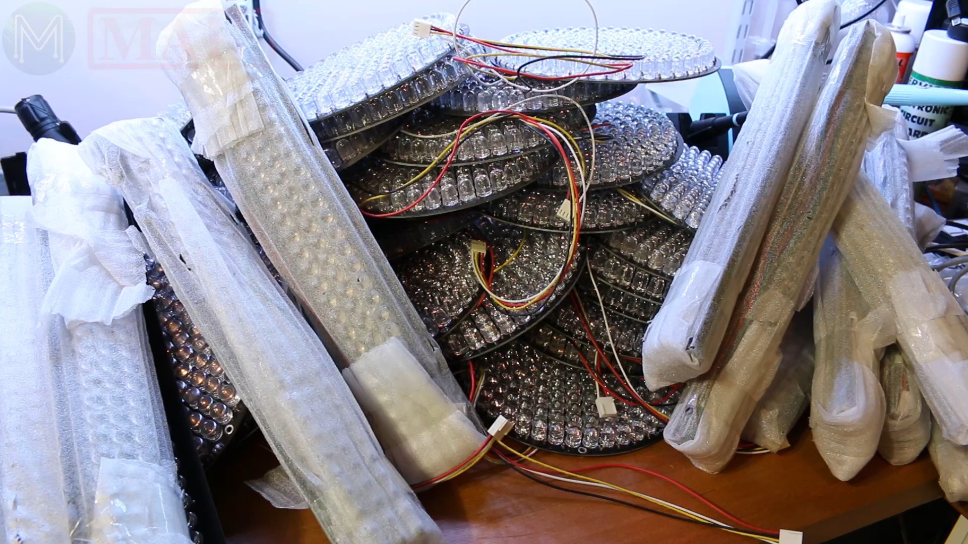
Motorized Sliders
My son managed to also pick up these, which are really cool. They’re not only a variable potentiometer, but they also have a motor on it. The idea is that you can adjust it to whatever level you want and control it by software. You would see them on mixing desks, where you can press a button and they all reset to a certain level. This is absolutely cool, and there’s a whole bunch of them. So I don’t know what I’m going to make out of it, but more than likely I’ll be using them for video editing because the interface with my software, often it’ll reset to a certain value. So I want to be able to just reposition it to a known point.
There’s a whole lot of other cables running off them. From what I can see… We’ve got power and ground, and two separate potentiometers.
So I’m just going to measure the resistance and see what pin outs these are. So if I move that up … Okay. So it’s a five, five kilo ohm pot. Minimum is 34 ohms, and it seems to be fairly accurate too. There’s probably about a 10 ohm accuracy. So it looks like there’s two channels, which sort of makes sense. One for positioning and the other for the mixing desk. But I’m not sure what the white does.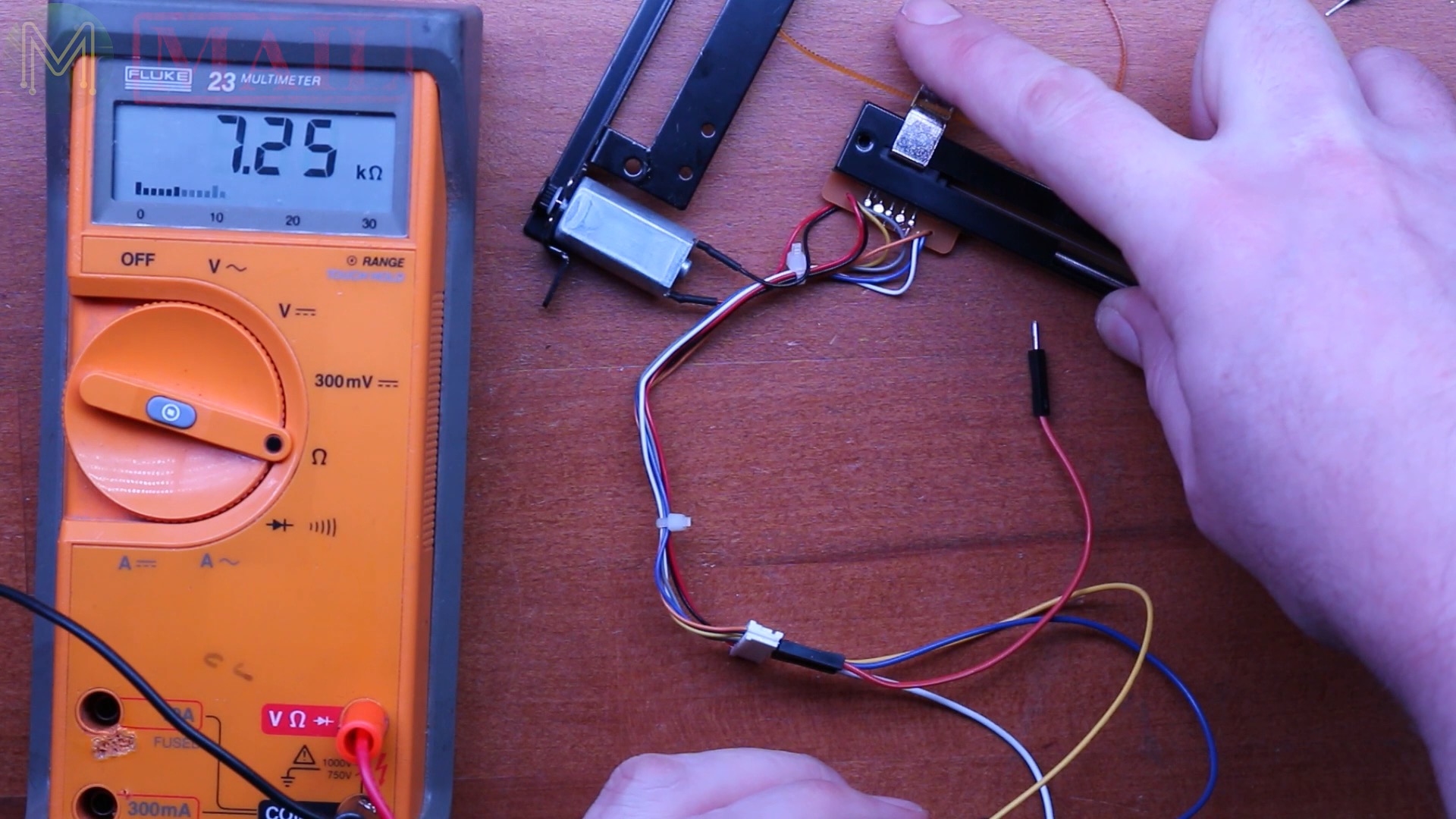
[EDIT: I’ve since discovered that these motorized sliders support capacitive touch sensors. This turned out to be the white cable.]
Now, unfortunately there’s not a heck of a lot of detail on these little motors. So I’ve set my bench power supply to 3V with a current limit of 500 mA.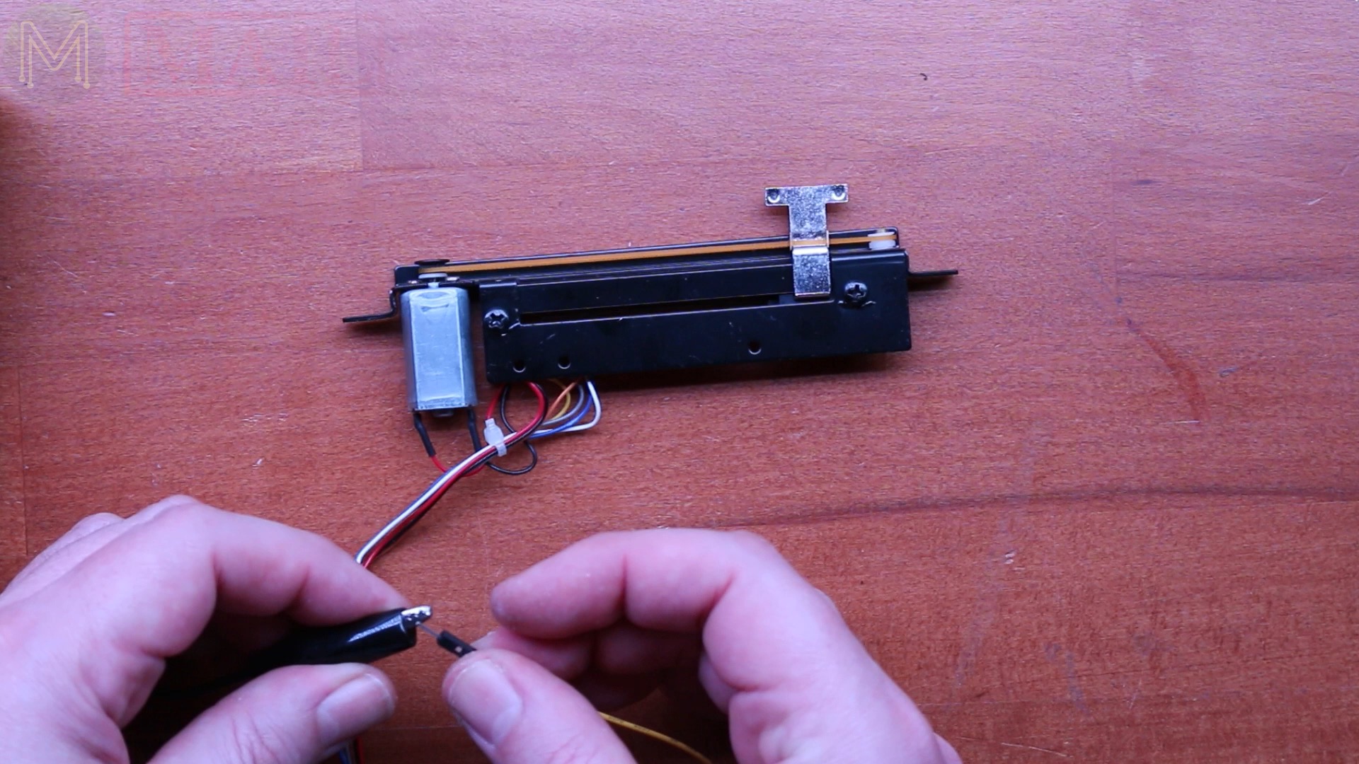
See what happens. That is absolutely perfect. So let me just reduce the current down a little bit, down to maybe 100 mA. So even 100 mA is pretty decent. To be honest, I probably wouldn’t drive it with much more than 100 mA.
You don’t want to have the cable potentially breaking with too much current and someone pushing on the slider. So that’s a pretty good test. I might try dropping it down to … Let’s try 50 mA. Fifty is just a little bit too low. Seventy a bit low. Eighty a little bit low. Okay, so the minimum I can get away with is 90 mA, but on the safe side, 100.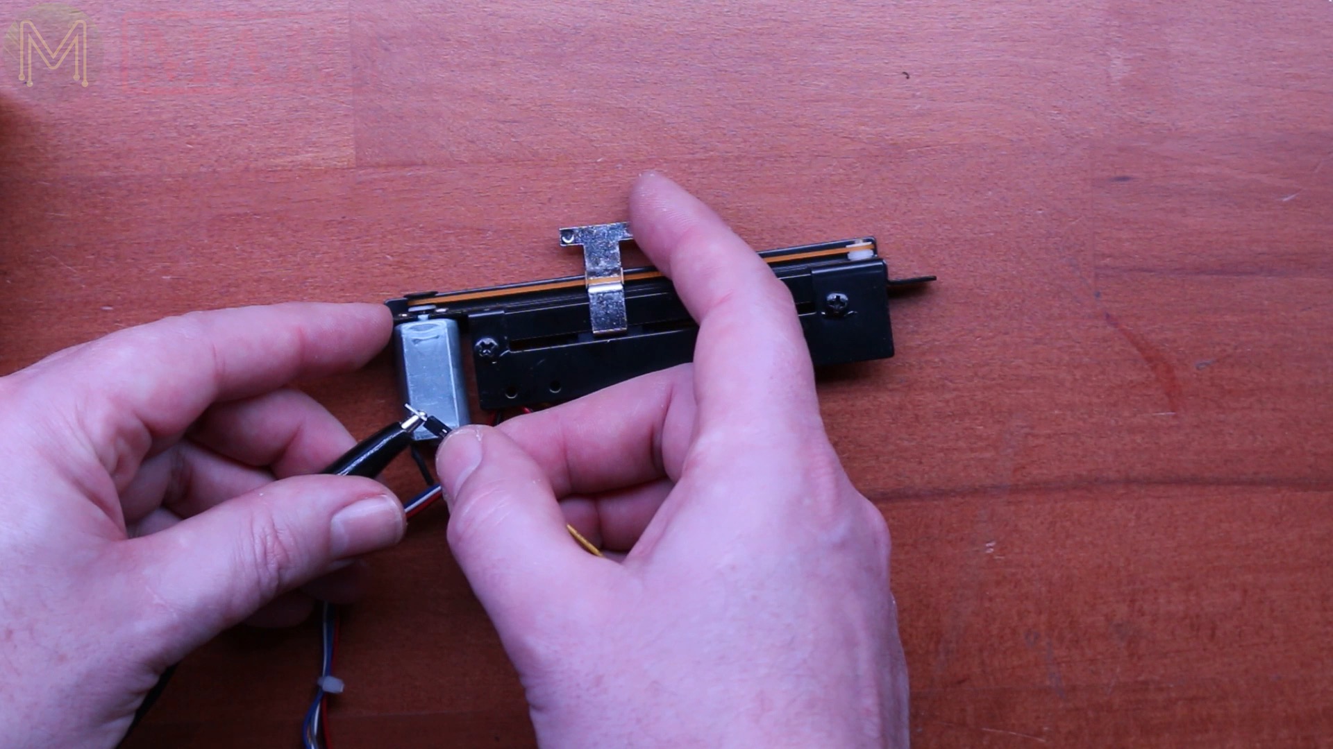
So that’s really good. 3V at 100 mA. I could quite easily drive it using a simple BSS138, as they’re cheap as chips. I am looking forward to this.
Once again, if you’ve got any ideas of what I can do, (I’ve got plenty of ideas), but if you’ve got any ideas, let me know in the comments below.
I think that’s about it for this week’s mailbag!
