What is I2C? How does it work? // Technology
What is I2C? How does it work? This is another QuickBits video giving you a brief overview of how I2C works.
A bit of history
I2C stands for Inter-Integrated Circuit and can also be called IIC or I squared C.
The initial I2C specification was created in 1982 and was designed to allow various Philips TTL, 5 volt ICs to communicate with each other at 100kHz. Revisions were added in later years that added faster bus modes, such as 400kHz, 3.4MHz and 5MHz.
- 1992 - 400kHz “fast mode” - multi master
- 1998 - 3.4MHz “high speed” - multi master
- 2007 - 1MHz “fast mode” - multi master
- 2012 - 5MHz “ultra fast” - single master There are other variants to I2C.
TWI
This was a standard created by Atmel and other companies to avoid trademark conflicts. This standard is identical to I2C, but lacks a high speed mode.
SMBus
There’s also SMBus, (latest specification here), which is a derivative of I2C developed by Intel which includes several differences:
- Packet Error Checking (PEC).
- Timeout for transfers.
- Standardized transfer types.
- ALERT line.
- SUSPEND line.
- Power down/up.
- Max. bitrate of 100 kHz/s.
PMBus
There’s also PMBus, which is a derivative of SMBus that adds power management capabilities.
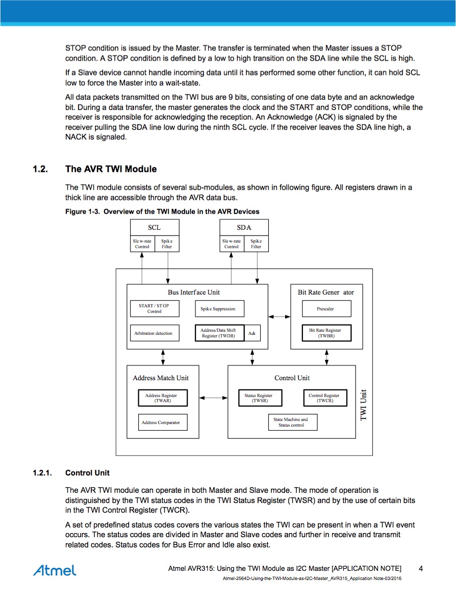
Electrical specification
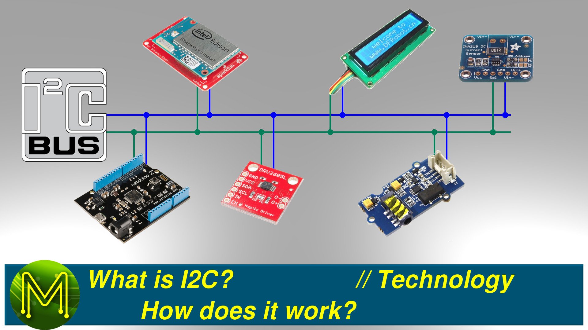
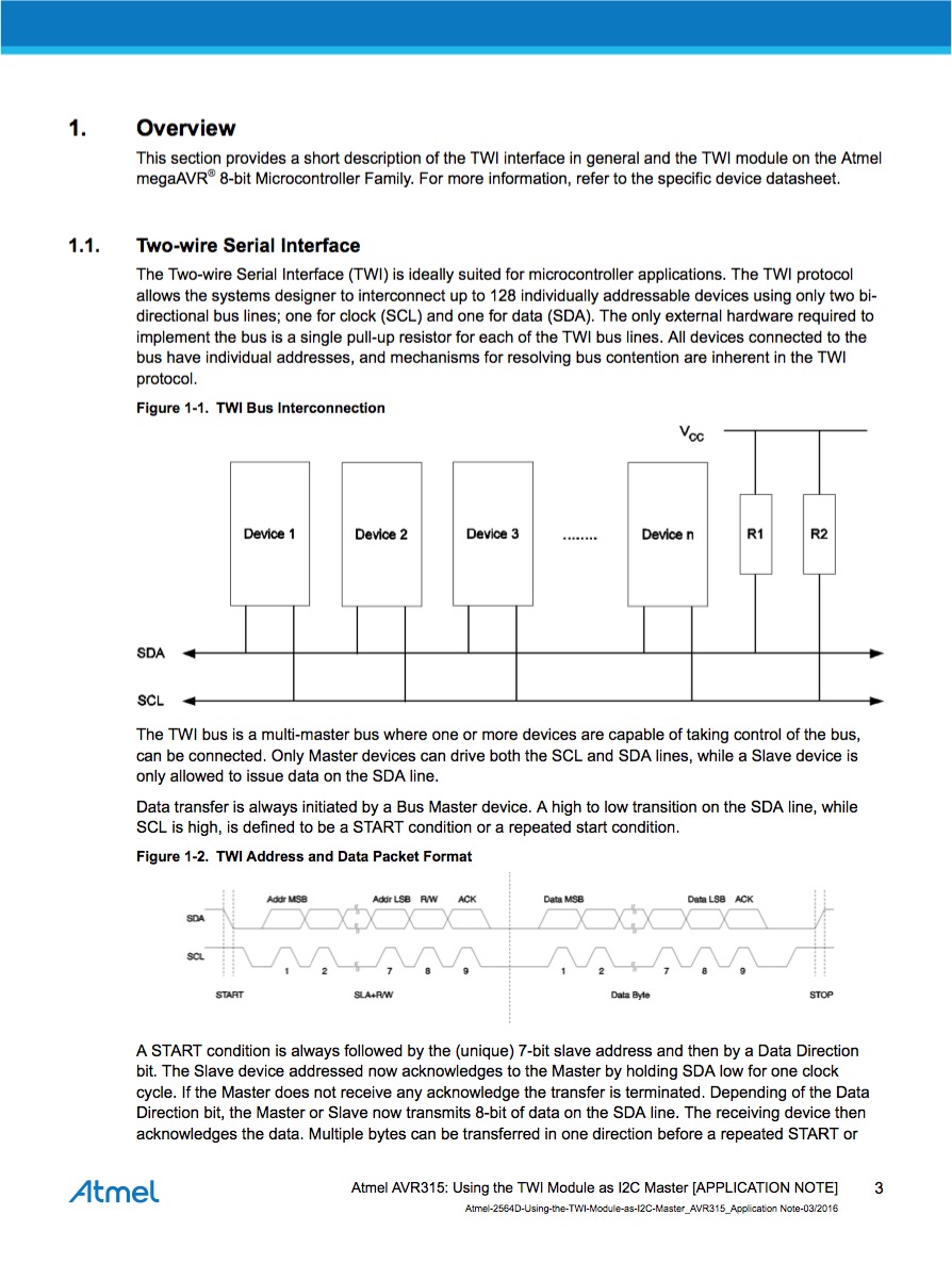
I2C is a two wire, bi-directional, multi-master, open-drain bus, which means master and slave devices can both transmit and receive.
- SDA - data
- SCL - clock
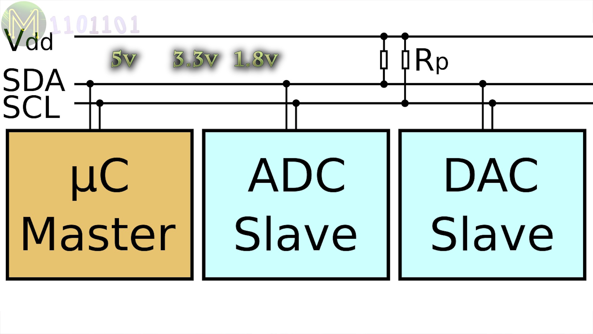
It can operate at 5 volts, 3.3 or down to 1.8 volts. This can make logic level shifting a bit more complicated, but these days most people use the common and cheap BSS138 MOSFET to handle this.
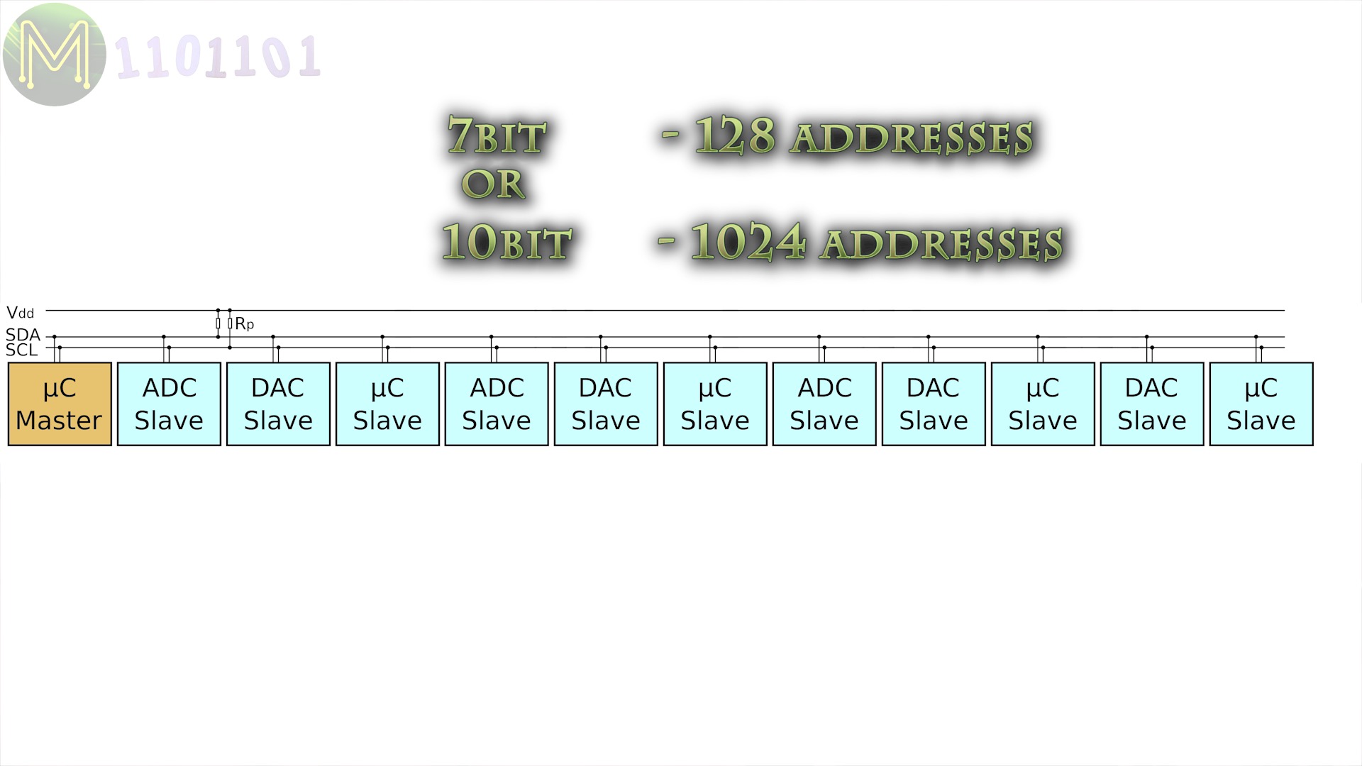
Since I2C has open-drain outputs that pull the lines down you will need to add pullup resistors on all devices. Values from 1K to 10K ohms are often used.Devices connected to this bus can sit anywhere on a 7 or 10 bit address space and operate in the same manner as MAC addresses on an Ethernet network. This means you can have up to a theoretical maximum of 1024 devices.However, in practice you are limited by two factors; address space clashes & bus capacitance.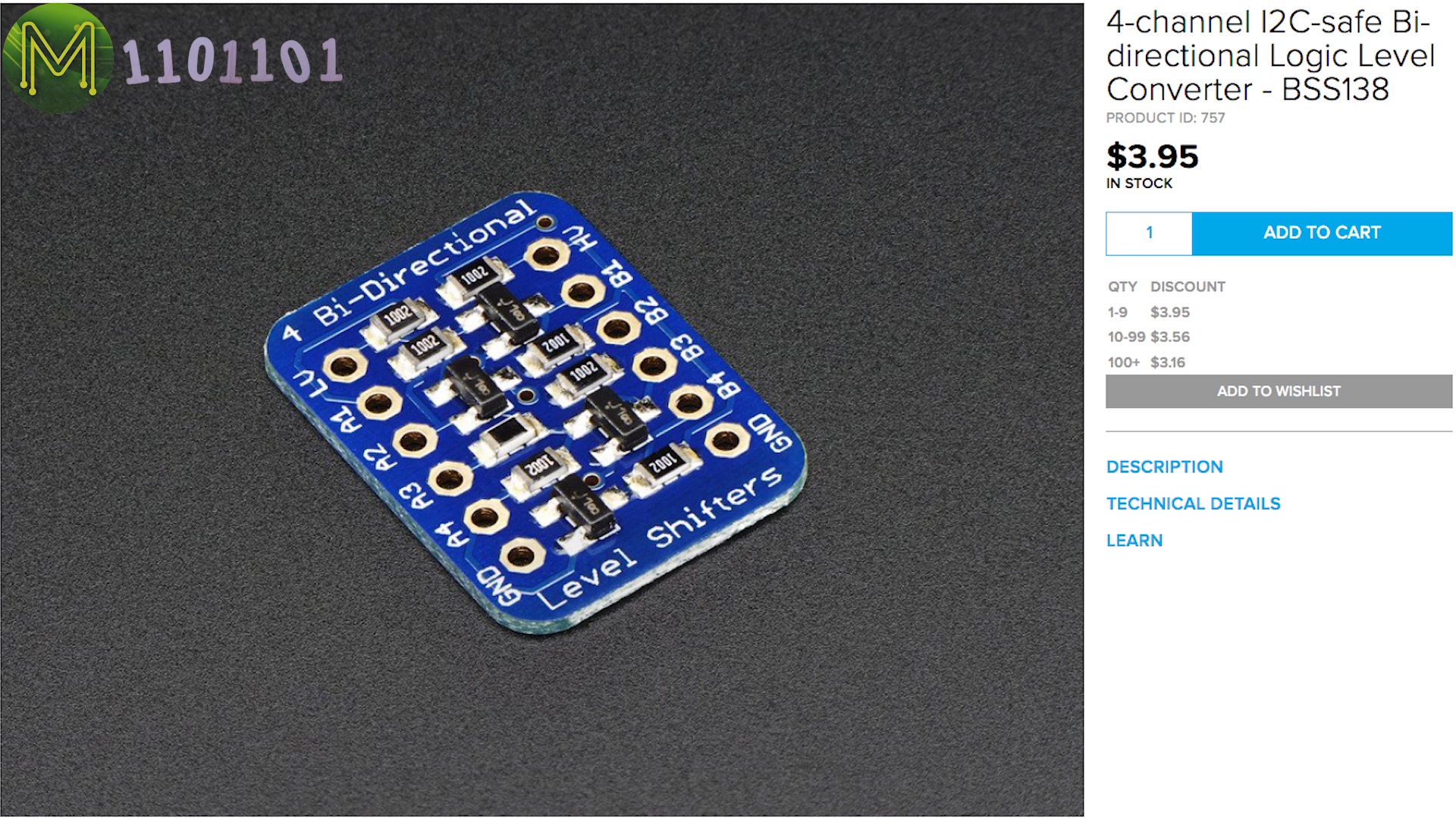
Address space clashes
There’s no real standard for address assignment, so you often have the scenario where device addresses will clash.
This can be resolved by bus multiplexers, but will add more complexity to your circuit.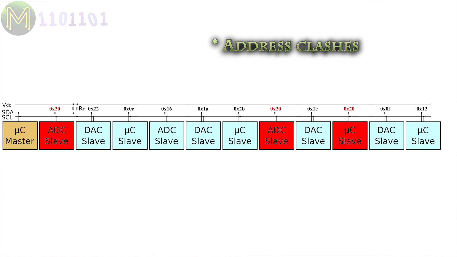

Bus capacitance
The lower the operating voltage, the greater the effect of capacitance caused by wires and tracks resulting in signals rising and falling more slowly and also cross-talk across wires.


So, you either have to lower the clock rate or shorten your wires when using lower voltages.
This limits the practical length of an I2C bus. The theoretical maximum is 1m. However, in practice, this is much shorter.
I2C protocol
The I2C protocol uses a fairly simple put/get model, transferring data one byte at a time with the master always setting the clock rate. So, there’s a fair amount of protocol overhead.
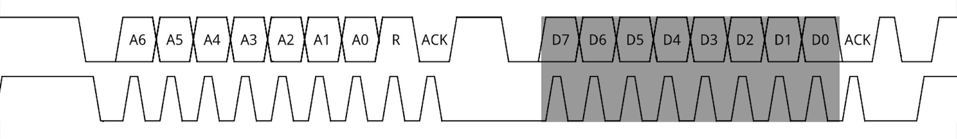
Write operation
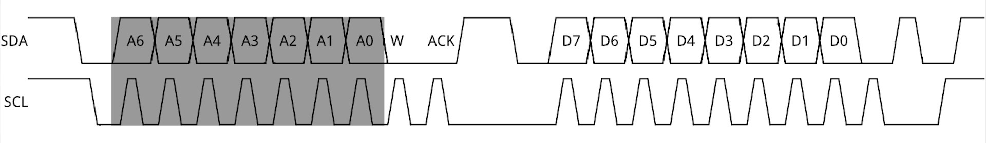
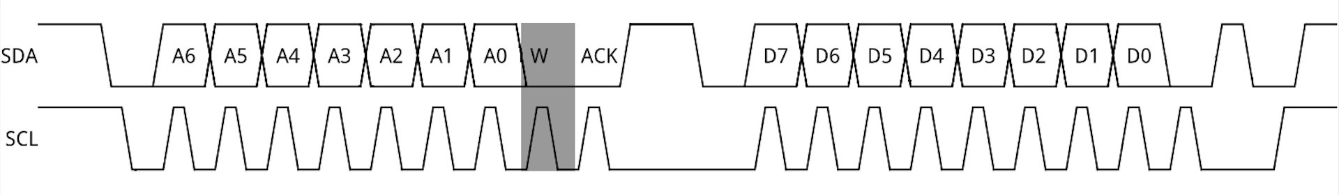
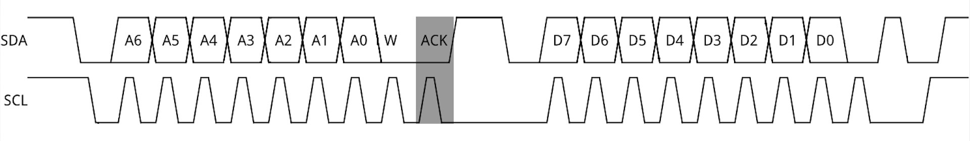
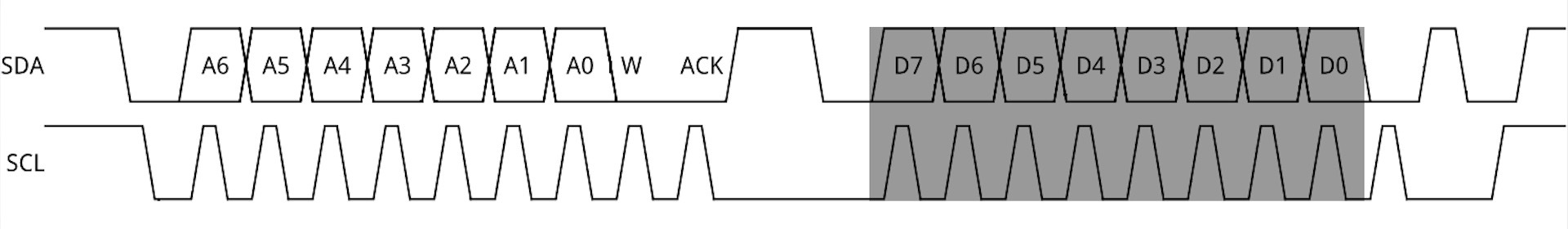
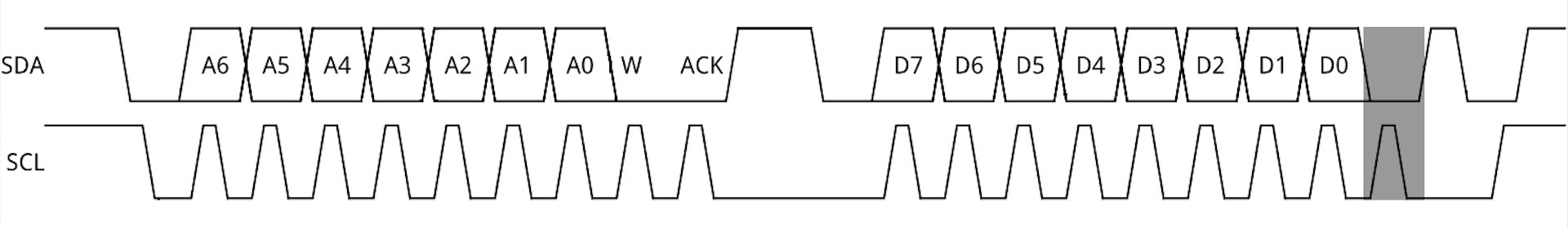
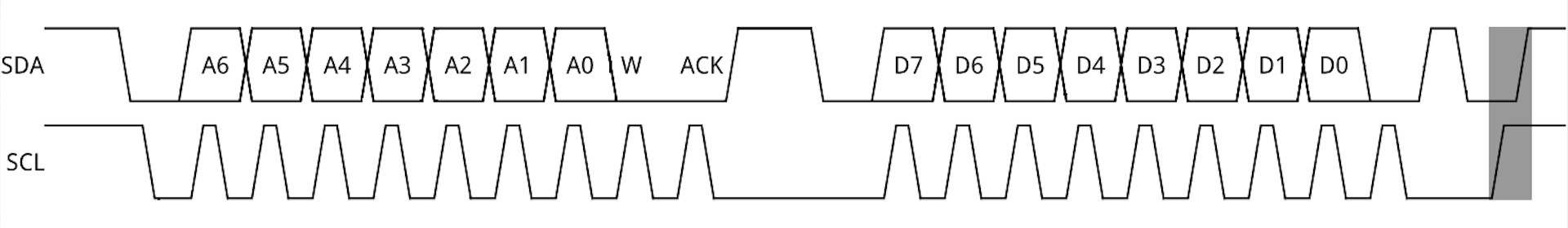
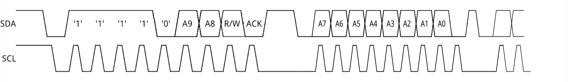
A typical 7 bit address write interaction will be:
The master pulling SDA low to indicate the start sequence.Followed by an address frame, with the first 7 bits being the address.and then a low on the 8th bit indicating a write.The slave should then respond with an ACK by pulling the SDA line low on the next clock.Then the master will send an 8 bit I2C register number,with the slave responding with an ACK.Followed by the data payload,and a slave ACK.Once complete the master will indicate a stop condition, where SDA is pulled low and then high just after a low to high transition of SCL. SCL and SDA are then kept high to free the bus.


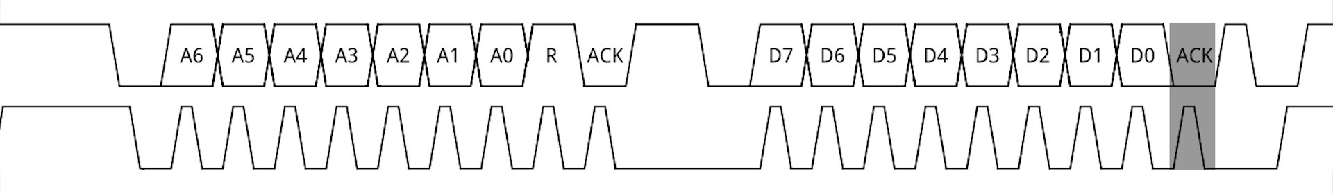
Read operation
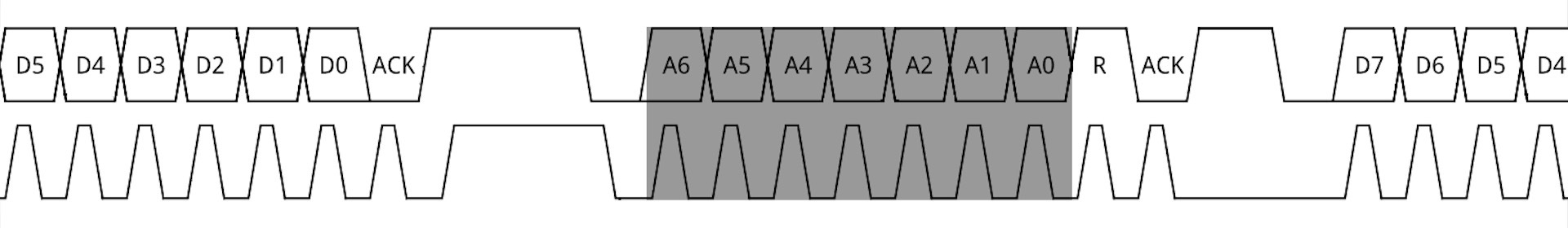
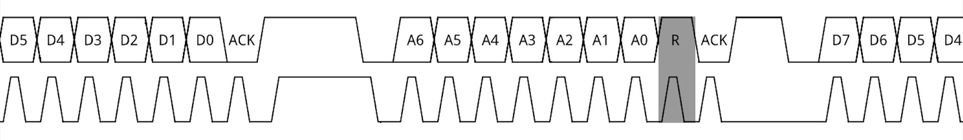
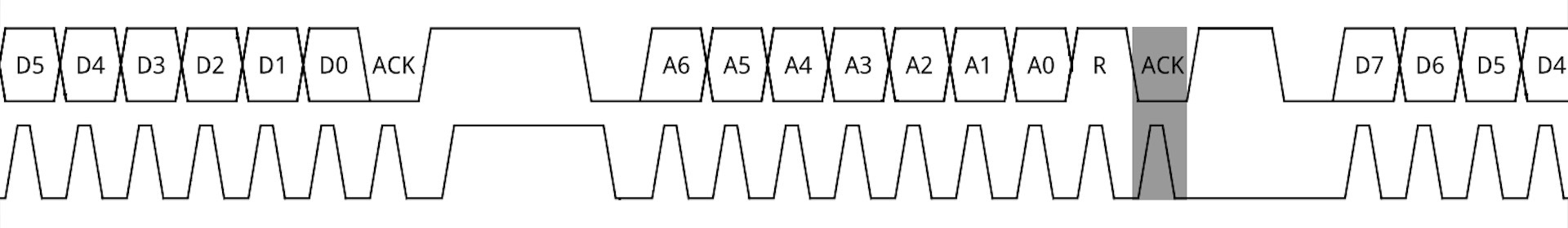
When reading from a slave the sequence initially starts out the same as a write:
The master pulling SDA low to indicate the start sequence.Followed by an address frame, with the first 7 bits being the address.and then a low on the 8th bit indicating a write.The slave should then respond with an ACK by pulling the SDA line low on the next clock.Then the master will send an 8 bit I2C register number,with the slave responding with an ACK.But this is where it deviates.
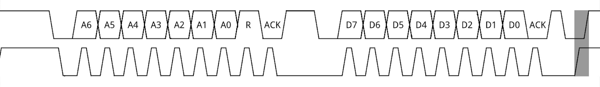
At this point the master will send another start sequence,followed by an address frame, with the first 7 bits being the addressbut the 8th bit high indicating a write.Another slave ACK,followed by the slave sending 8 bits of data back to the master.With the master sending an ACK back to the slave on the next clock.Once complete the master will indicate another stop condition freeing the bus.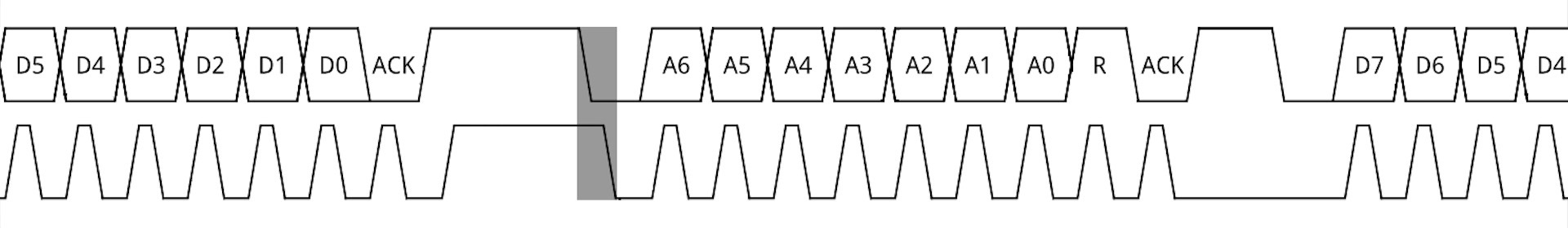
High speed mode
When working with high speed mode devices the protocol changes slightly.
The address frame extends out to include a master code which is transmitted at normal I2C clock rates but then starts clocking data at a faster rate for the rest of the interaction.Any device capable of high speed mode will recognize this special master code and drop into high speed mode for the duration of the interaction.Once complete all devices drop back down to normal clock rates.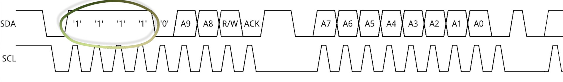

Ultra Fast Mode
With the 5MHz Ultra Fast Mode things change even further.
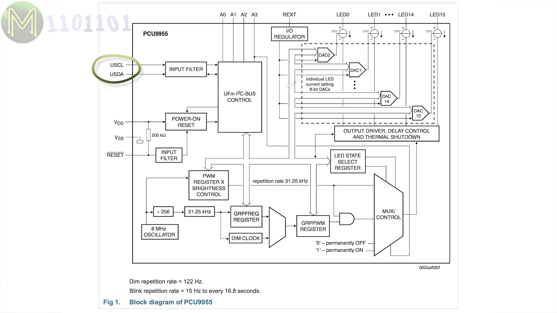
- The SCL and SDA lines are used in a similar way to USB and ethernet lines.
- It’s a uni-directional protocol, so slaves don’t send any ACK response and there’s no multi-master capability.
- There’s also only 112 addresses available.
- So, UFM is used for write only devices, such as LED strips and displays.
Bus arbitration
Bus arbitration is fairly basic, but works well. Every master device on the bus will monitor the SDA line even whilst sending.
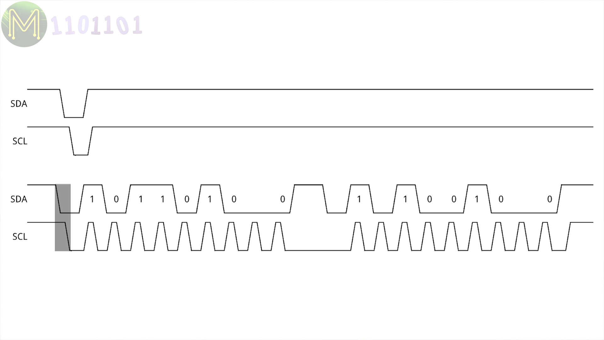
The first to pull the SDA line low indicating a start sequence will win the arbitration.
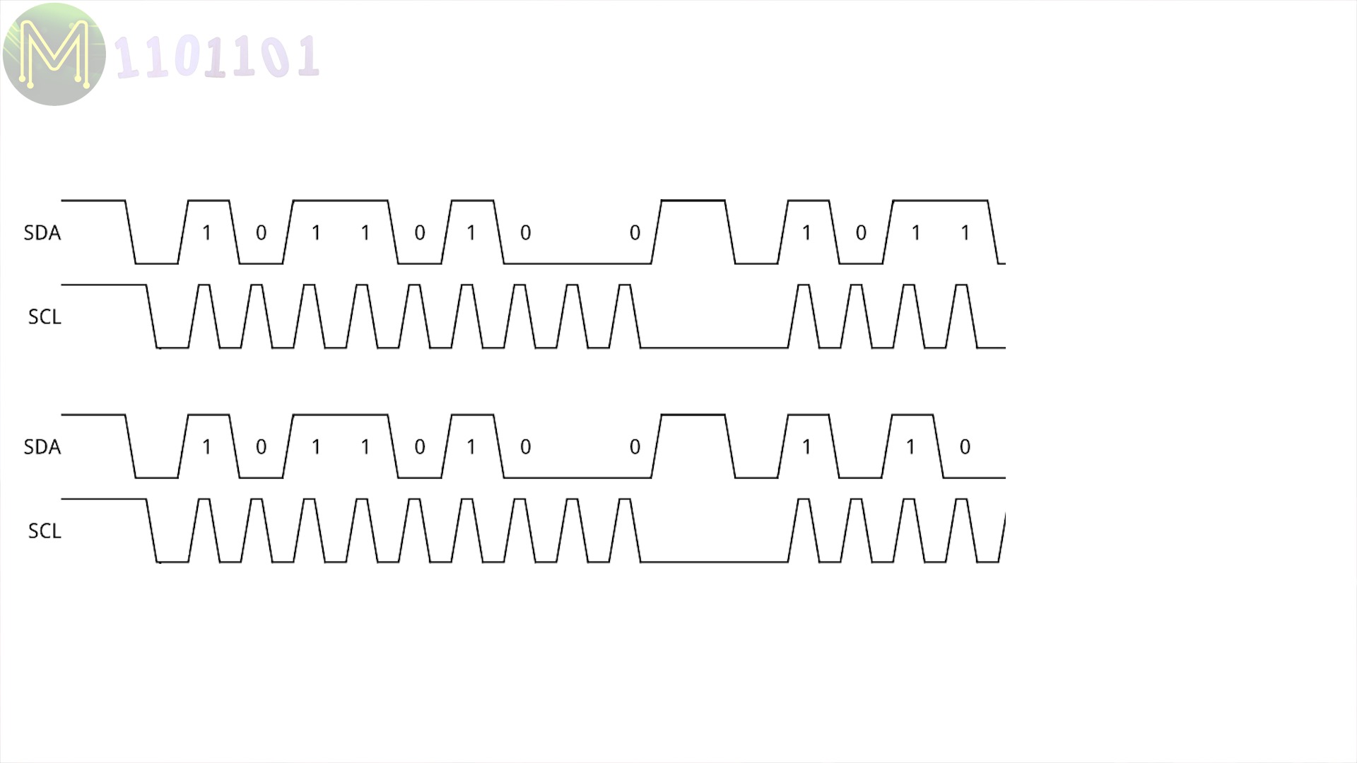
In the, unusual but possible, event of two masters transmitting data at exactly the same time as in this scenario,
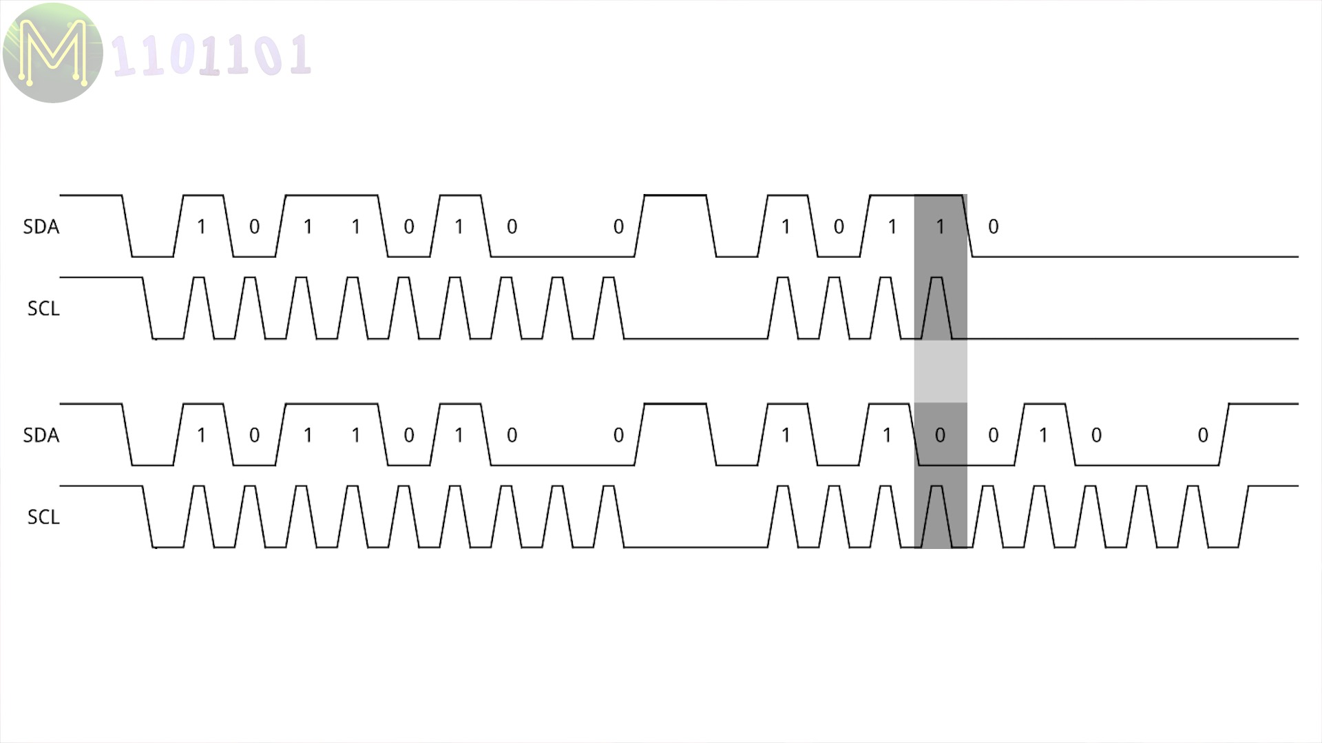
the master that detects a difference on the bus will back off and become a slave until a stop sequence is seen from the other master.
Another way of looking at it is; the master that wanted SDA high, but was pulled low by another master will lose. So bus arbitration extends for the duration of the interaction not just the beginning.

Note that slaves can transmit on the bus but will always be clocked by a master and don’t possess the same bus arbitration that exists on a master.
Masters can actually “claim the bus” by not sending a stop sequence, but instead continuing on talking to as many slaves as it wants to.
Clock stretching
When a slave is sending data to the master, it is the master that controls the clock, but sometimes the slave isn’t ready to send data back to the master. If this happens the slave can pull down the SCL line, at which point the master will detect this change and will not take any action until the slave releases SCL.
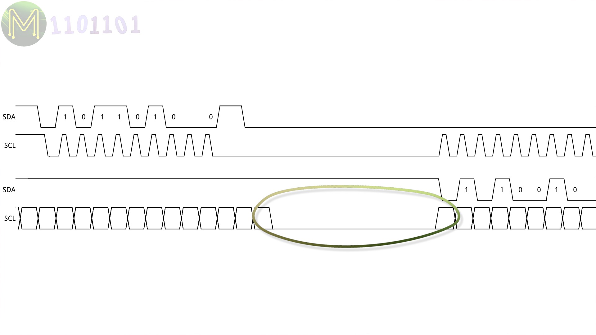
This is called clock stretching and is a primitive form of flow control.
Common issues
I2C is a fairly straight foward interface, but there are a few things to watch out for:
- Bus speeds - Make sure all your I2C devices on the bus operate at the same speed, otherwise you’ll see bus arbitration issues.
- Termination - Ensure you have pullup resistors on SDA and SCL for every I2C device on the bus, otherwise you could potentially see the bus hang and be non-responsive.
- Logic levels - Some 3.3v devices are 5v tolerant, but not all. So always check your voltages!
- Cable length - At higher speeds keep your cable length short. Heck, at any speed keep your cable length short.
- Dodgy devices - Some devices don’t fully adhere to the I2C spec and don’t have an open-drain SCL. These types of masters won’t work on a multi-master bus nor support clock stretching.
- Software - Some I2C software implementations, aka bit bashing, don’t fully adhere to the spec and you’ll see lots of bizarre issues there.