
How to use WS2812 LEDs - A simple Wiffy counter in GoLang - Project
The WS2812 RGB LED is a pretty popular device that’s been around for a long time. In this video I’ll cover what they are, how to drive them from 3.3v logic and even throw in a simple GoLang library to control them from a Raspberry Pi which will display a count of wiffies! What more could you ask for?
What is a WS2812?
A WS2812 is a small 4 pin semi-conductor that is powered from 5v DC, so of course it has 5v and GND pins.
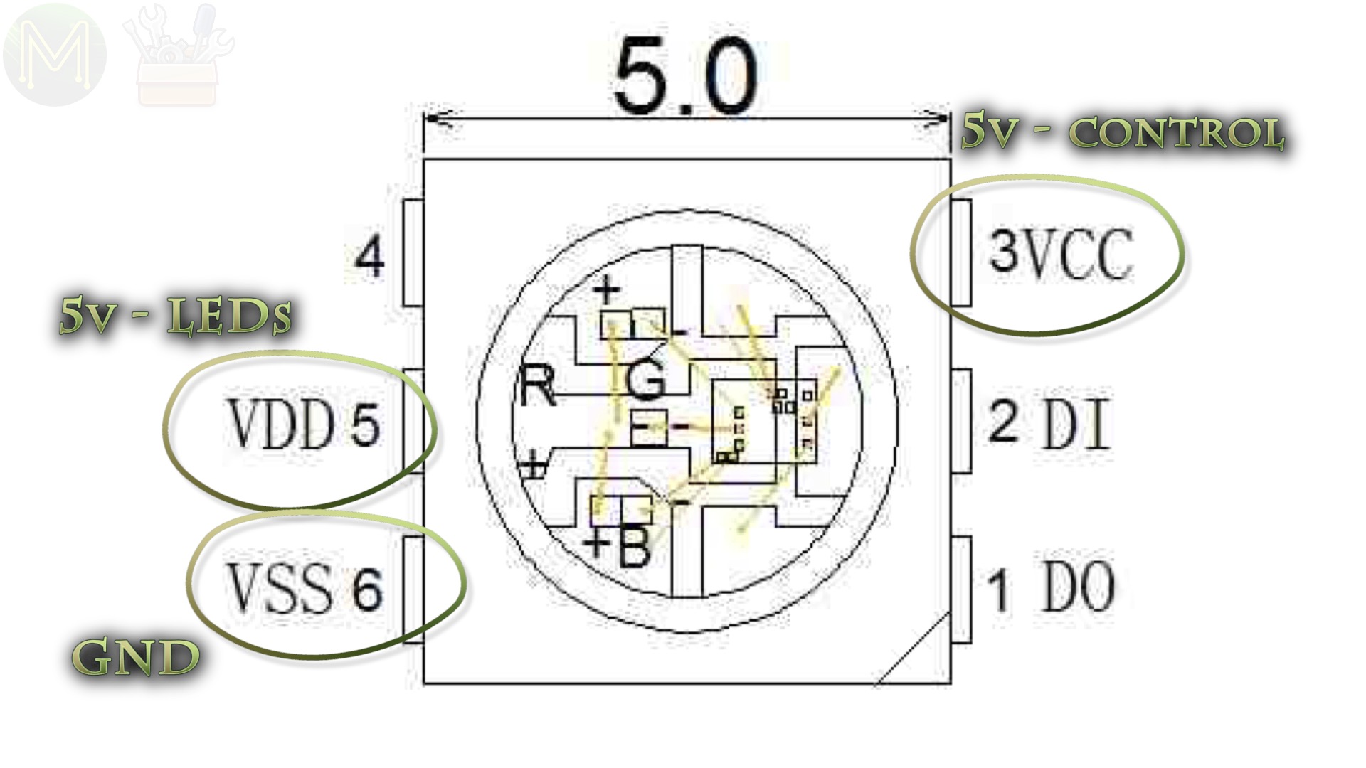
It also has data in and data out. These last two pins allow each LED to be daisy chained. Serial data coming in one end is buffered and transmitted out the other end.
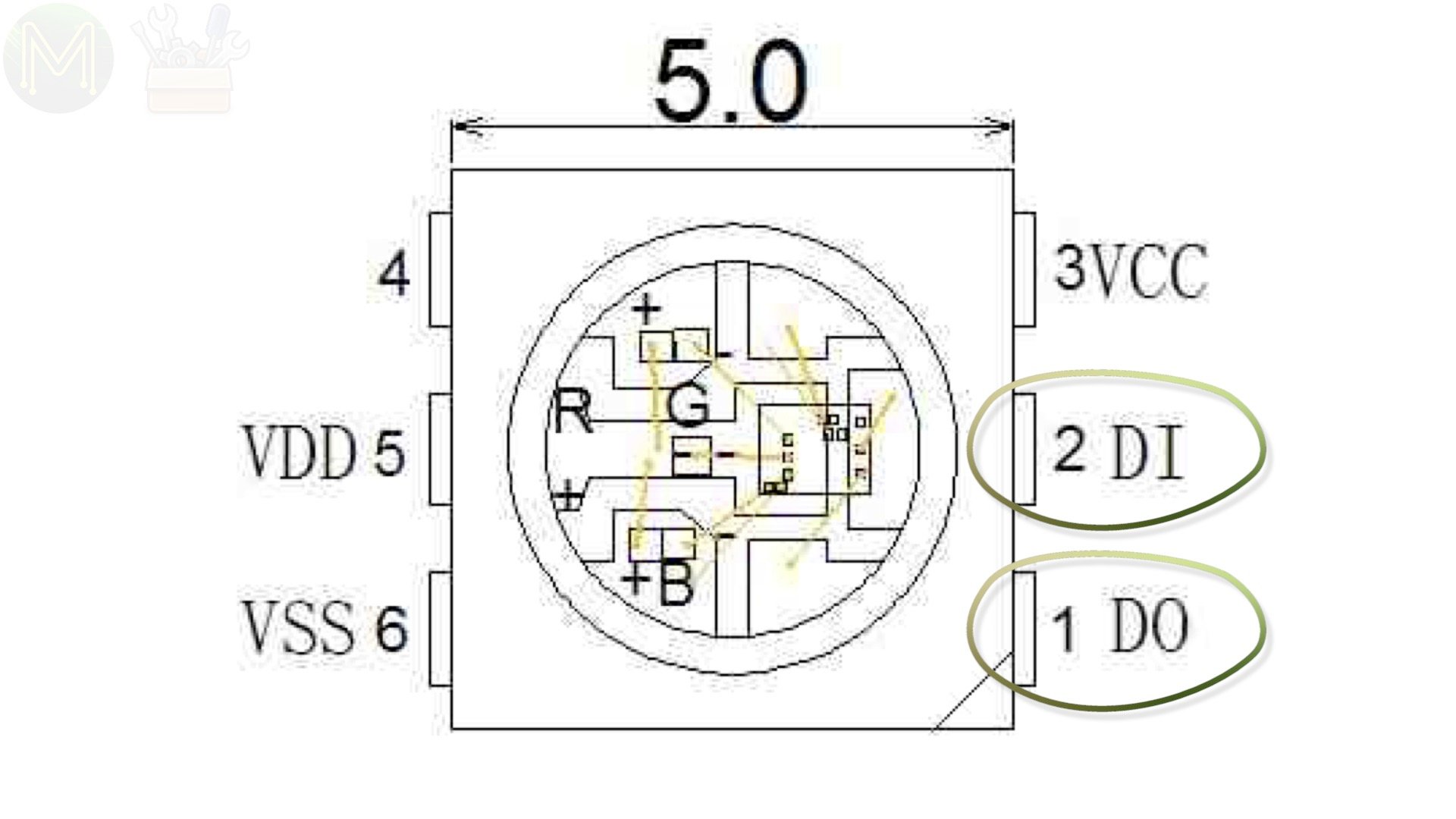
This allows them to be daisy-chained to theoretically any length.

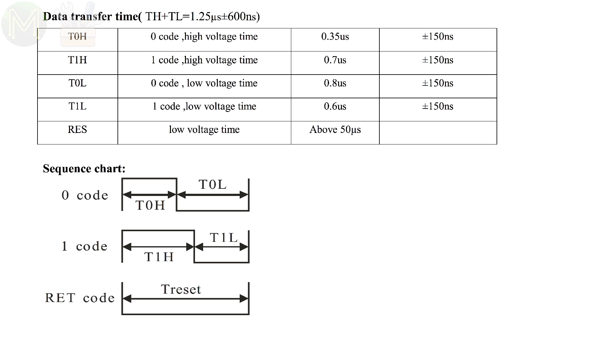
The “serial data” is actually a Pulse Width Modulated signal with a typical signal frequency of 800kHz. The PWM signal doesn’t need to repeat for the display to refresh, because the LEDs will latch on to that state and will only change when a new signal is transmitted. This signal is very time sensitive. Any slight delay and it’ll affect the output. So, any MCU or SoC capable of PWM will be able to drive them.
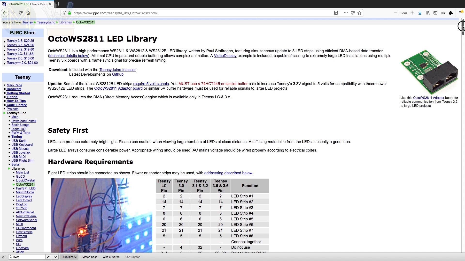
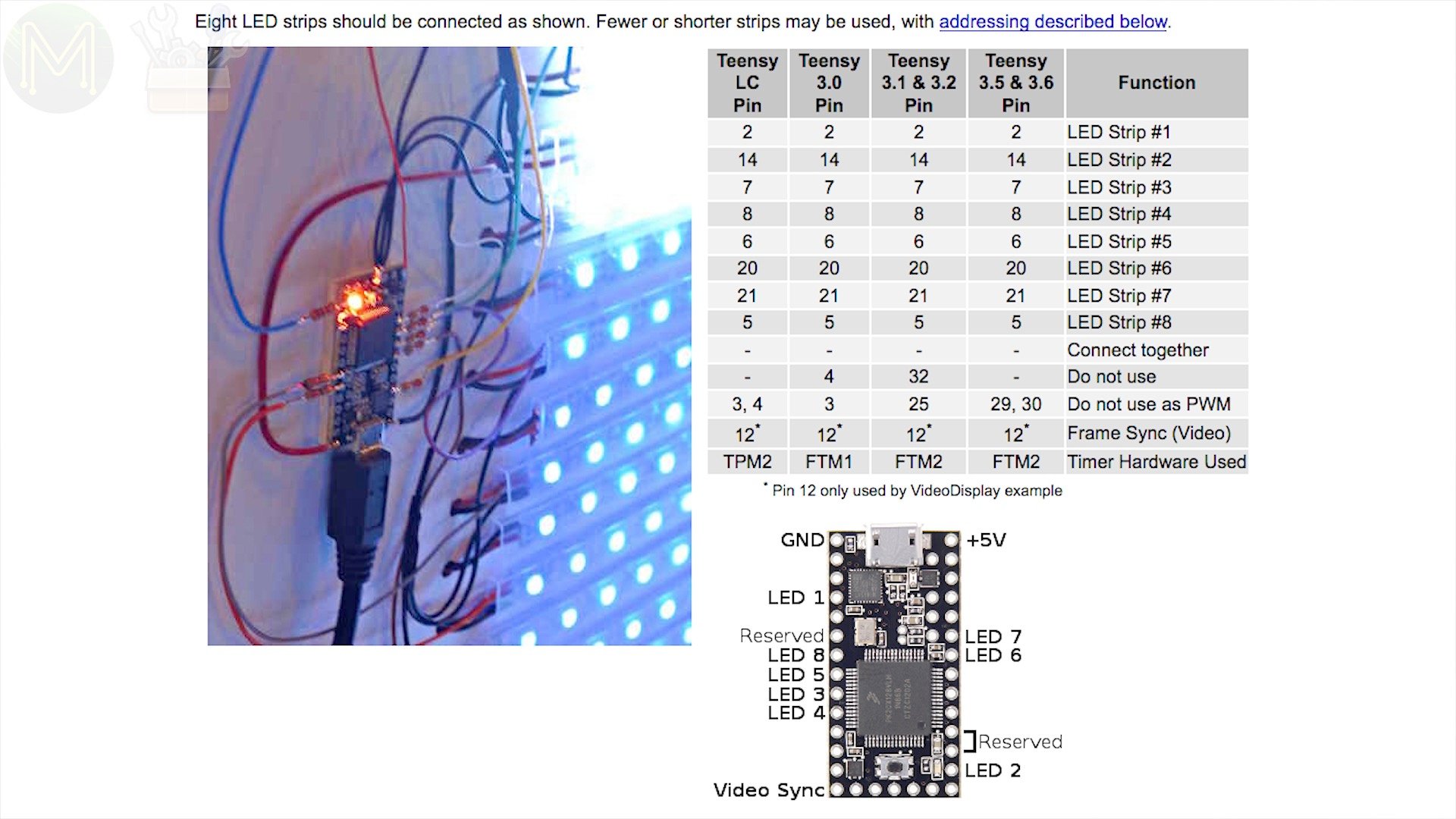
When driving a couple of LEDs, you can do it with plain old bit-bashing, but when driving thousands, forget doing this in software as these LEDs need to have pretty reliable timing. You also might have issues when using a non real-time O/S as it will often be busy doing other things like user input. Most people wanting to drive a handful of these use an MCU like any of the Arduino boards, but if you want to drive 1,000 of LEDs, then you will need to move to a fast MCU like the Teensy.
How many can you drive on one chain?
Theoretically hundreds of thousands, but there are three problems that you will come across the more LEDs you add.
FPS
The first is refresh rate. Since this is a serial interface; the more LEDs you add, the longer it takes to refresh all of them. People often call this “frame rate”. If you want any display animation, then 24 FPS is the gold standard for humans. [If you want to know why, then check out the video in the description below.]
If you don’t want to go below that 24 FPS magic number, then the maximum number of LEDs is 1,388.
- (800000 / 24) / 1388 = approx. 24.01537 FPS
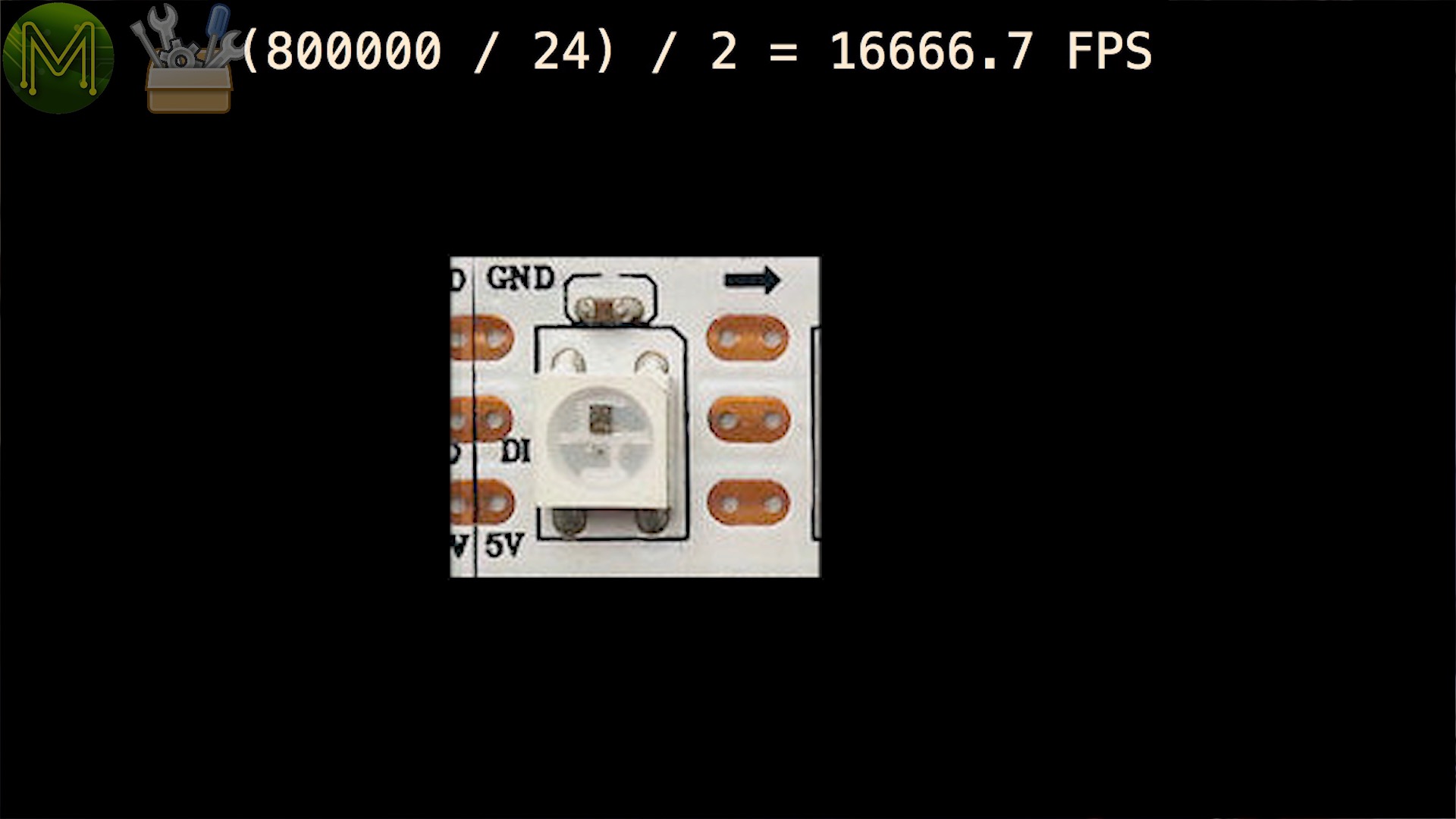
Of course, if you’re not doing any animation, then you could drive 2000 or 4000 on a single strip.
- (800000 / 24) / 2000 = approx. 16.666667 FPS
- (800000 / 24) / 4000 = approx. 8.3333333 FPS

You can get around this by segmenting off LED strips and as long as you have enough CPU grunt behind them, you can drive several simultaneously. The Teensy is one such MCU that can do this well.
Power
The second issue is power. The longest LED strip you can buy is around 5m with 300 LEDs.

One of the reasons for this is that copper is not a perfect conductor and so has a resistance. This resistance will cause a voltage drop, so by the time you get to the end of 5m you will find that you may have around 4v or even as low as 3v depending on the quality of the LED strip.

Another reason for limiting the length is that each LED will draw up to 60mA when fully on and around 1mA when off. So, an LED strip with 300 LEDs can draw a maximum of 18A. This means that the copper tracks at the start of the chain have to be able to cope with 18A being shunted through it. Since they are mostly thin copper they will start to get pretty hot.
There is a way around this though. You can segment off each strip and power at intervals, but this only works for matrix displays as you will introduce yet more issues if you use multiple power supplies along the chain.
Another way around this is to use a higher voltage, and hence a lower current for the strips. 12v is the usual standard. These strips also contain small voltage regulators providing 5v for the LEDs, with the PWM logic level signal still at 5v. So, you can get much longer strips with higher brightness.
Memory
The third issue is memory. If you want to keep track of what you’re displaying, then you’ll need to store this somewhere. For an SBC this is no problem, but for an MCU it becomes a limiting factor. Each LED adds 3 bytes of storage, since there are red, green and blue LEDs.
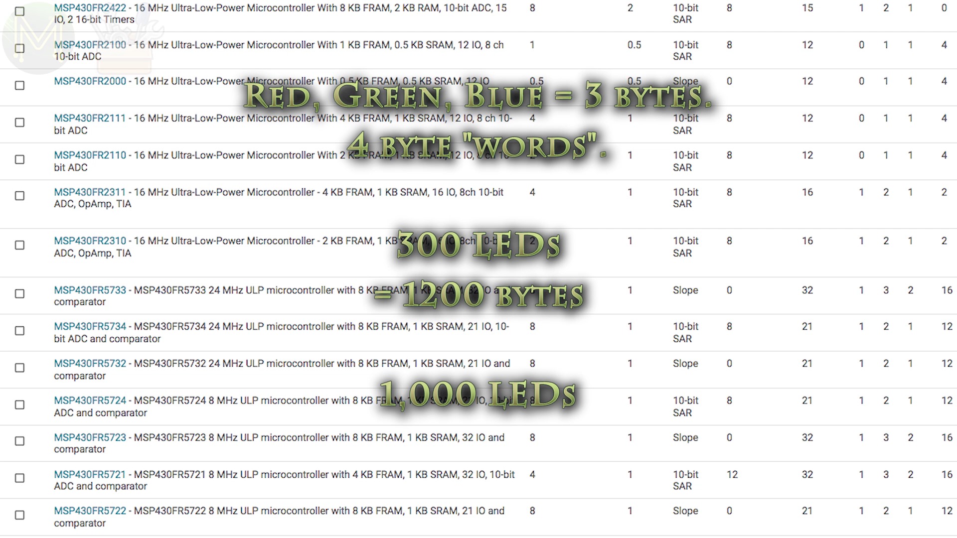
Unless your code is very efficient, this will actually use up 4 bytes of storage per LED. So, 300 LEDs requires 1200 bytes of RAM and 1000 LEDs will need 4K RAM. Doesn’t sound like much, but this is a lot for an MCU. Considering 4096 bytes is usually all you get, leaving only 96 bytes for code data.
Interfacing
Apart from those three factors there’s one last thing you need to consider and that is interfacing. Most WS2812s will accept only a 5v PWM signal, but there are some that will work with 3.3v logic levels. Alas you won’t really know until you try them out. So YMMV.
If you’re using 3.3v logic levels as in a Raspberry Pi or a lot of the MCUs you get, then you’ll need a logic level converter, or buffer.
There are several ways of doing this, but since this is a uni-directional interface, (that is one way), it makes things a little easier.
Method 1 - direct connect.
The first method is just a plain direct connect and hope that the WS2812 handles the logic high being at 3.3v. Not very reliable, but works sometimes.
Method 2 - diode drop.
Typically, a logical HIGH will be seen when the PWM voltage hits at least 70% of Vcc.

If you drop Vcc down on the first LED by inserting a diode, then 5v becomes 4.3v.

That means the 3.3v logical HIGH ends up being above 70%. The first LED will then buffer the signal and re-transmit at 5v logic levels. So, you’re essentially using the first LED as a logic level converter.
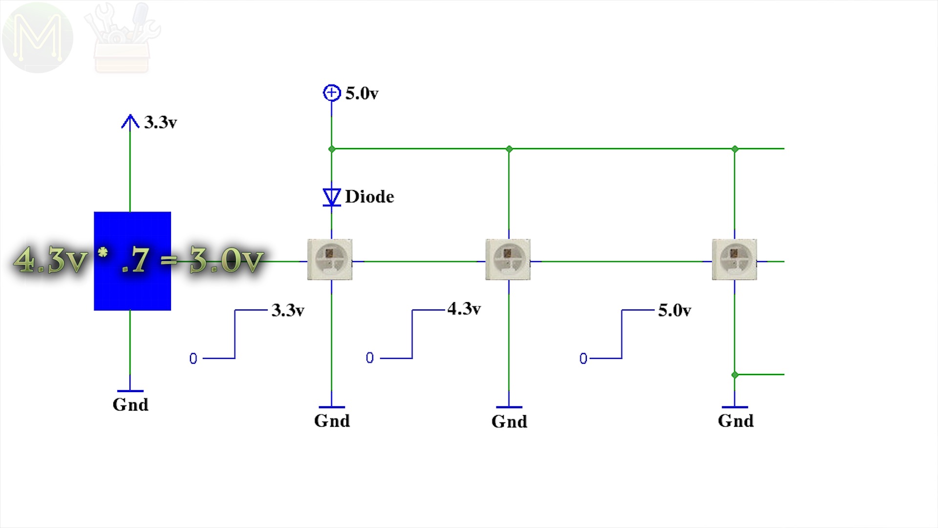
It’s probably the simplest way of doing it, but not reliable in all situations.
Method 3 - diodes.
Another way is to use a diode offset circuit.
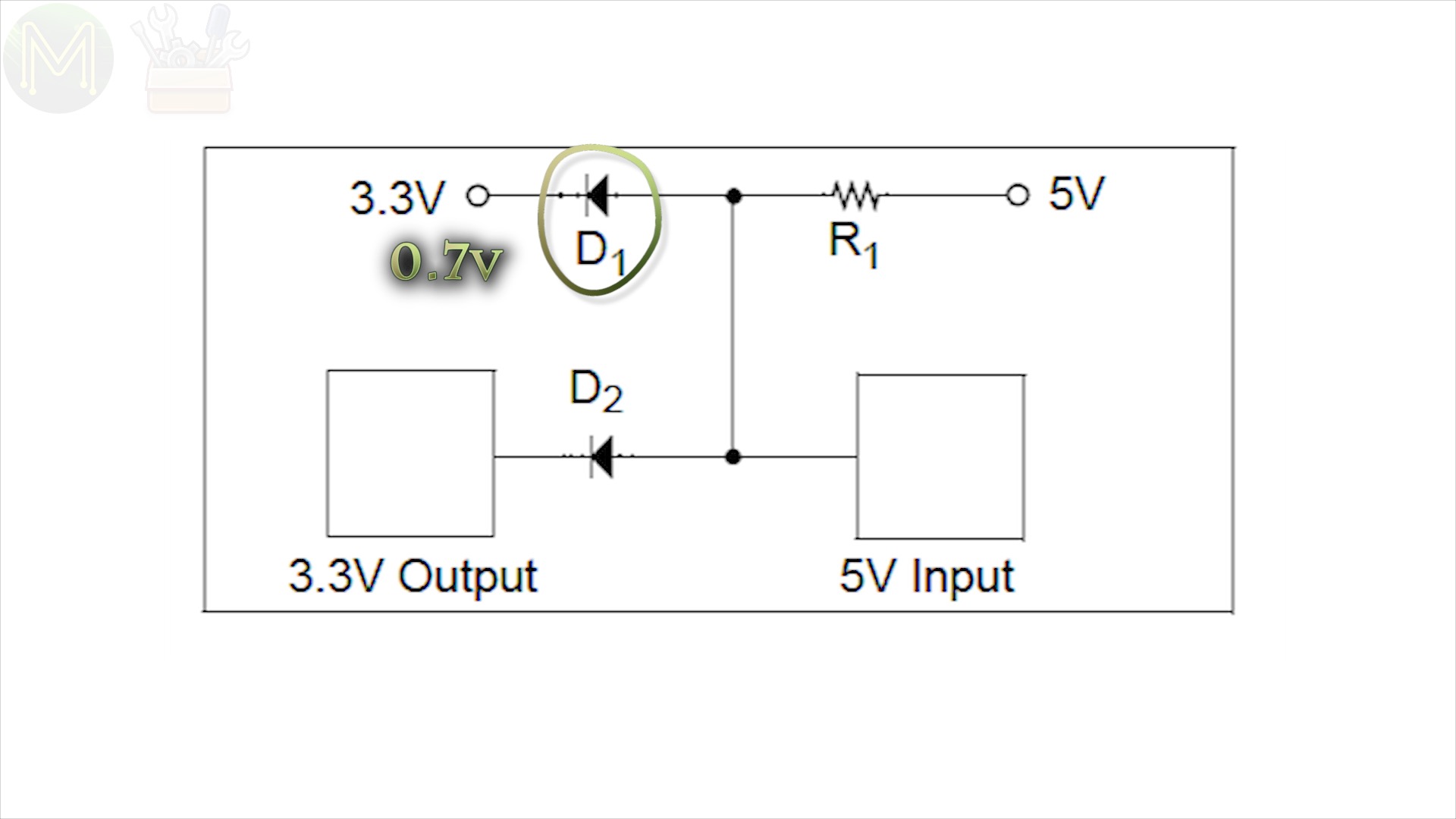
In this case the output low voltage is increased by the forward voltage of diode 1, around 0.7v. You end up with 1.1v on the WS2812, which is still interpreted as a logic low.

For a logical HIGH the resistor and diode 2 will create a voltage at the WS2812 of 0.7 above Vcc, or 4.0v.
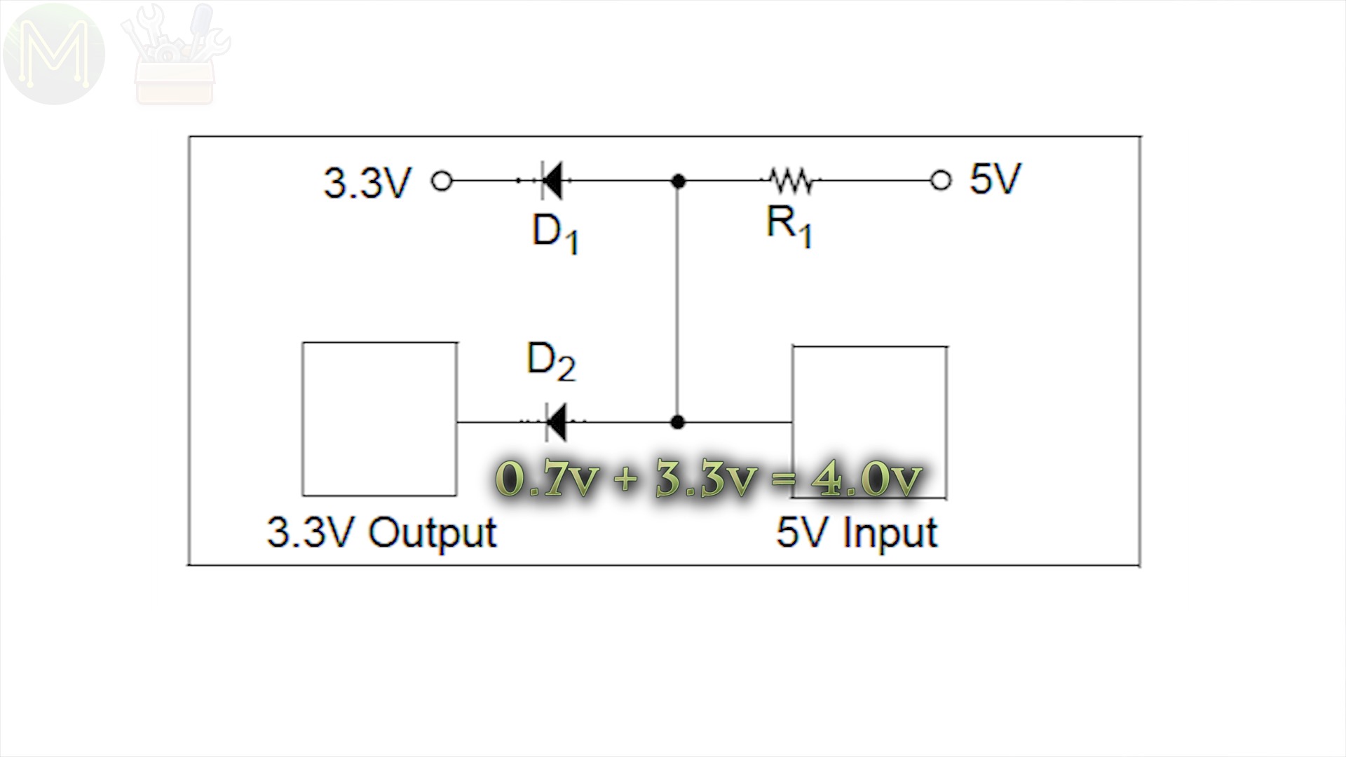
This is, of course out of spec for the driving side, but if the current is low enough, there shouldn’t be any issue… Possibly… Maybe.
Method 4 - op amps.
If you’re worried about going out of spec, then you could use a voltage comparator circuit.
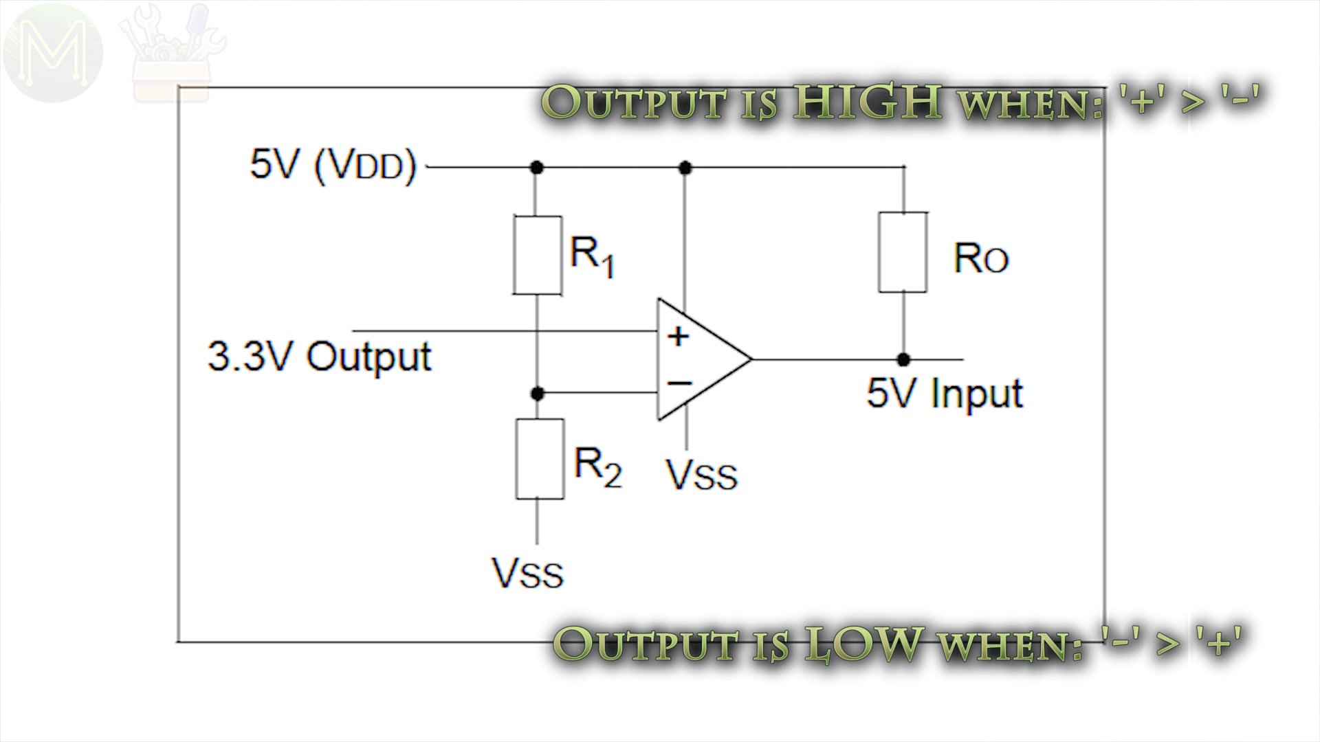
This simple circuit will drive to ground the output, when the inverting input is greater than the non-inverting input. For a logic HIGH, the inverting input will be lower than the non-inverting input. The two resistors set the voltage at which this occurs.
Method 5 - BSS138 MoSFET.
You could try and use a classic BSS138 MoSFET as a logic level converter, but these don’t really perform well at 800kHz.

At most you can get around 200kHz out of them. So are decent enough for low speed I2C and SPI, but not good enough for WS2812 signal speeds.
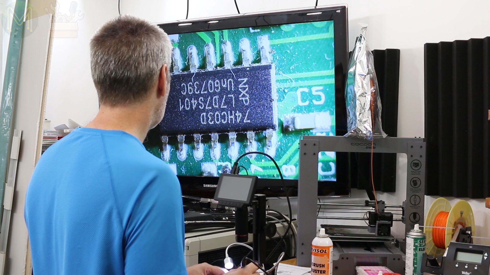
Method 6 - 74HCT245
One of the better ways is to use the 74HCT245 analog switch.

This IC is not only capable of handling the 800kHz signal frequency but also provides 3 switches. It’s a 5v powered IC, but it can handle 3.3v logic levels, so makes an excellent logic level converter for the WS2812s.
Software
Now that you have everything all sorted out, there’s the software side. Since these LEDs have been around for many years, there’s a tonne of APIs and libraries for everything from the Arduino IDE, Python, C, C++, C#, Rust and GoLang.
Of course, since I’m a GoLang fanboy I’ll be using Go on a Raspberry Pi. To be able to use Go, you’ll need two libraries:
- The Raspberry Pi ws2812 C library - https://github.com/jgarff/rpi_ws281x
- And the GoLang package bindings for that library - https://github.com/mcuadros/go-rpi-ws281x/
If you’re a regular viewer of my channel, then you would have seen my last Maker Speed Run video, where I designed the PiStryp in under a week. As I mentioned in this video, one of the things that was lacking on this board was a buffer. So my RGB LED strip worked OK, but when I tried Seon’s 7 segment NeoPixel display it didn’t.
I’ll be addressing this design flaw in my next version of the PCB, but in the mean time I needed to breadboard it up to confirm the design. I didn’t have any 74HCT245s in my stock of components, but digging through a bunch of PCBs I eventually found one and soldered it up to a SOIC breakout.
I used the PWM interface on the Pi, but you can also use the SPI and PCM interfaces just as well.
Writing some simple GoLang code I was able to drive them without issue. Scoping out the input and output, you can see that there is a 15nS delay between switching with a 42nS rise time.

Pretty good response for an analog switch.
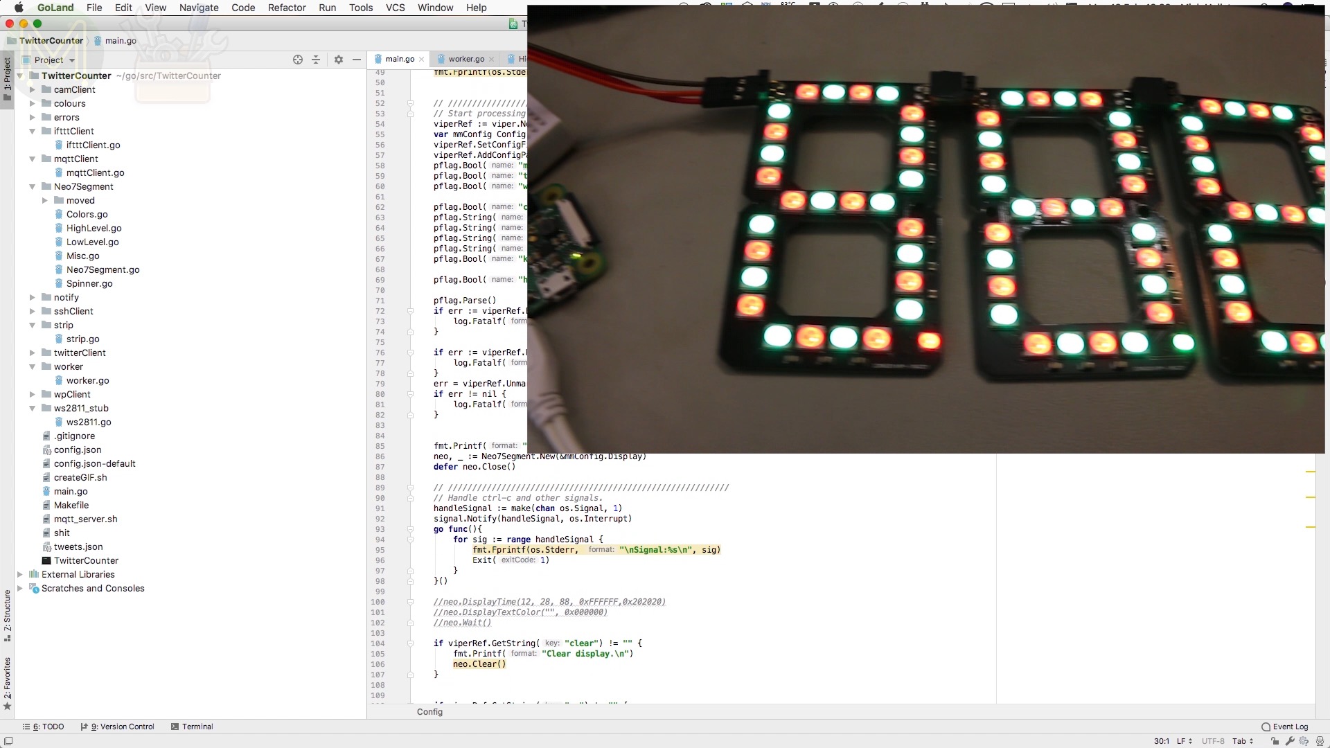
So, since I had Seon’s NeoPixel 7 segment display up and running, I might as well write some high level code to map text to pixels. I wrote a GoLang package similar to Seon’s C++ interface and you can find this on my GitHub page.
So, there you go. Easy!
Counting WiFis
If you’re a regular viewer of my channel, then you’ll also know about my WiFi problem. This channel has been going long enough for it to even have it’s own Official WiFi Counter. So, instead of using Seon’s display to just count subscribers, I reckon I need to count WiFis.
This isn’t as complex to do as you might think. To do this I wrote it in two parts.
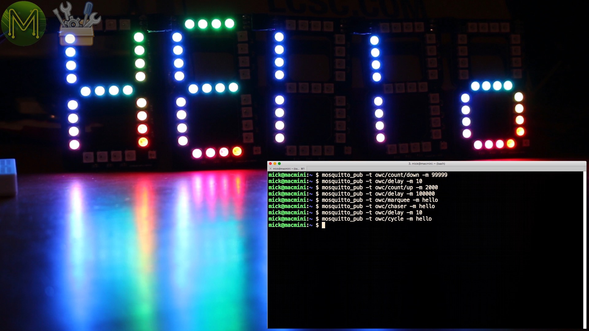
One part makes the display an MQTT client. So you can publish things like count down, count up, display text in a plain colour, or alternating colours. If you want to setup an MQTT server, then check out my QuickBits video on how to do this with a Raspberry Pi.
The second part is a Twitter to MQTT interface. There’s several ways of doing this. Since I’m using an MQTT client interface, I can use IFTTT to do the interfacing. If you saw my MQTT mailbox project, then you’ll see how I did it in that video.
But instead I decided to do it another way, which was to have another GoLang executable poll Twitter and if it finds certain text coming from a certain someone, it’ll fire off an MQTT message.
I ended up using this GoLang package to do this.
So, every time my Official Wifi Counter tweets the latest WiFi count, it’ll update my display. Later on I’ll add in a reply tweet with a photo taken using the Raspberry Pi camera.
The whole thing is driven from a simple JSON config file which allows me to set the polling rates and login details. It’s fairly straightforward code and you’ll find it on my GitHub page.
Summary
So, there you have it. All I have to do is wait for the next revision of the PiStryp to arrive this week which not only includes the 74HCT245 analog switch, but a bunch of BSS138s breaking out all of the Pis 26 GPIOs on to a 5v tolerant Pi header. I’m also making a more expensive version which uses the LSF0108 8 channel logic level converters. These will have signals capable of hitting 100MHz.

So, stay tuned to this channel, my website, or keep an eye on my Tindie store for details.
Thanks for watching and see you next week.