Building an MQTT letterbox. // Project
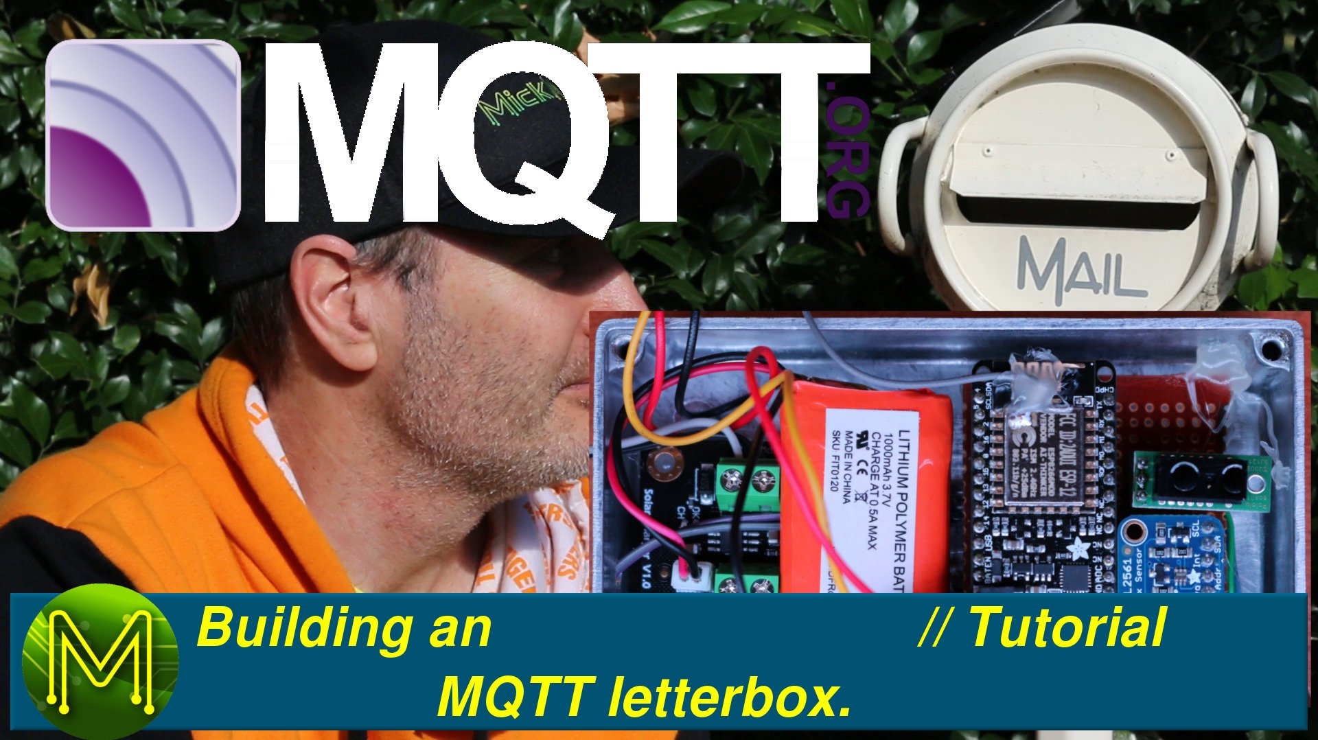
Remember that thing in front of your house? The letterbox. In this multi-part video I’ll show you how easy it is to get your letterbox to send you alerts via MQTT when you get new mail. So you won’t have to guess anymore.
Jamie’s quote
For those people who’ve been around the UNIX systems scene for years will know about Jamie Zawinski and his famous law of software envelopment, (aka Feature Creep), which is:
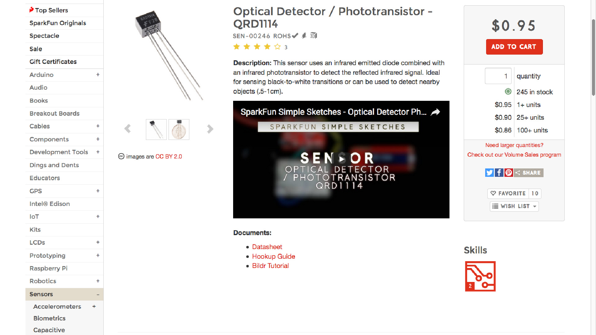
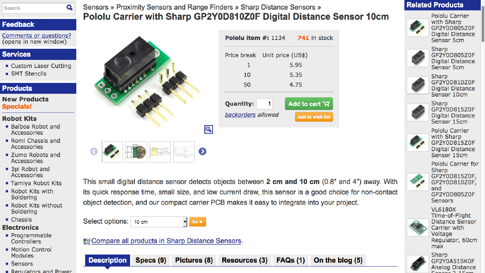
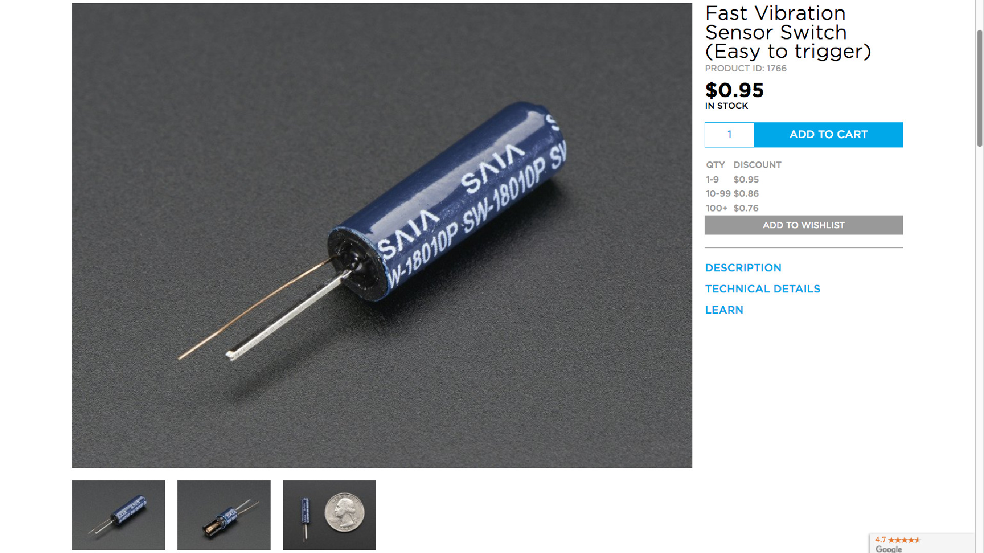
I didn’t want to use a PIR as I may get false readings, especially if the back flap was left open. Same story with ultrasonic sensors and most of them run off 5 volts which limits the choice of MCU.An IR shooting sensor could work, but would rely on some fiddly positioning in the mailbox. 5mA current draw was also a little high. Likewise Phototransistors would be fiddley to work with and would require more cables that I’d want.So, I eventually settled on this simple distance sensor, which is capable of responding to an object between 20 and 200mm away. Perfect size for my mailbox and there won’t be any noisy bounce or false triggers.I also needed something on the flap that was cheap and reliable. This Fast Vibration sensor would do the trick and is dirt cheap.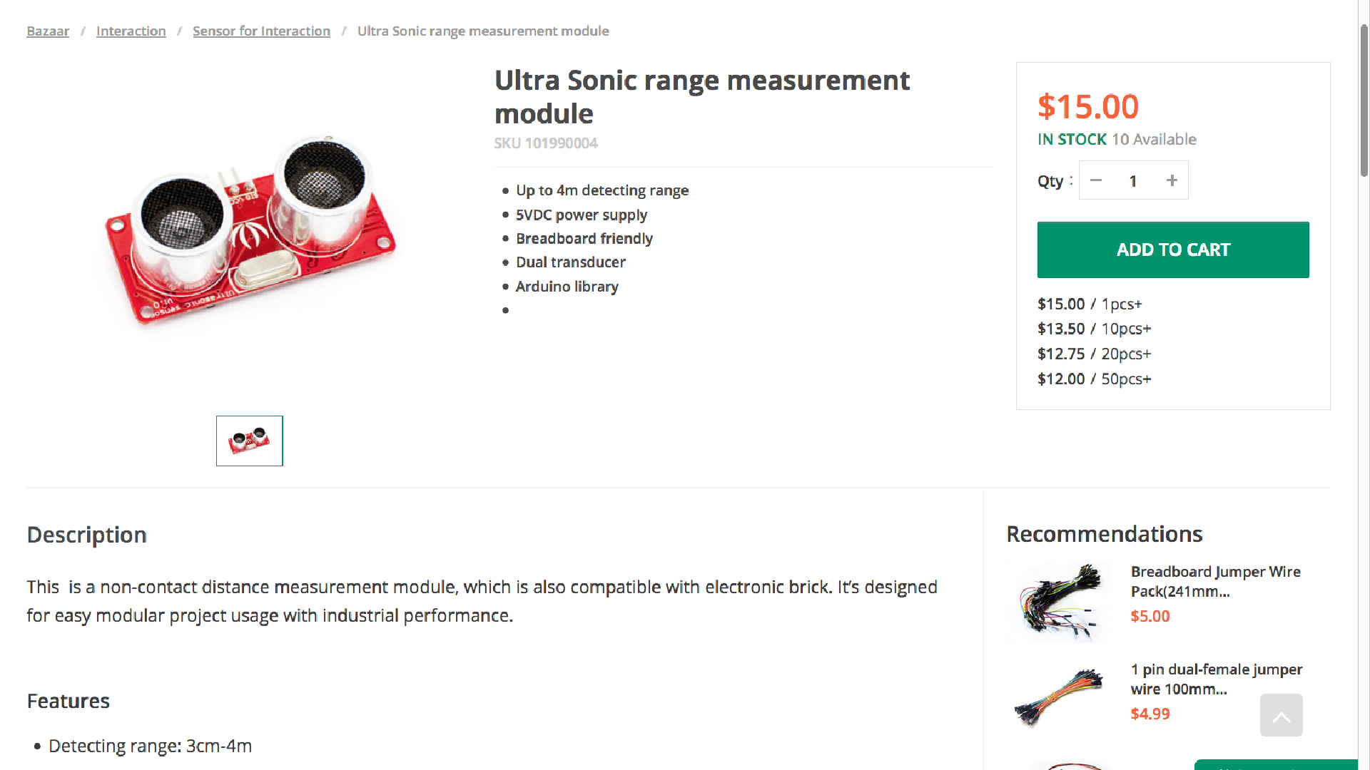


So, the complete Bill Of Materials ended up being:
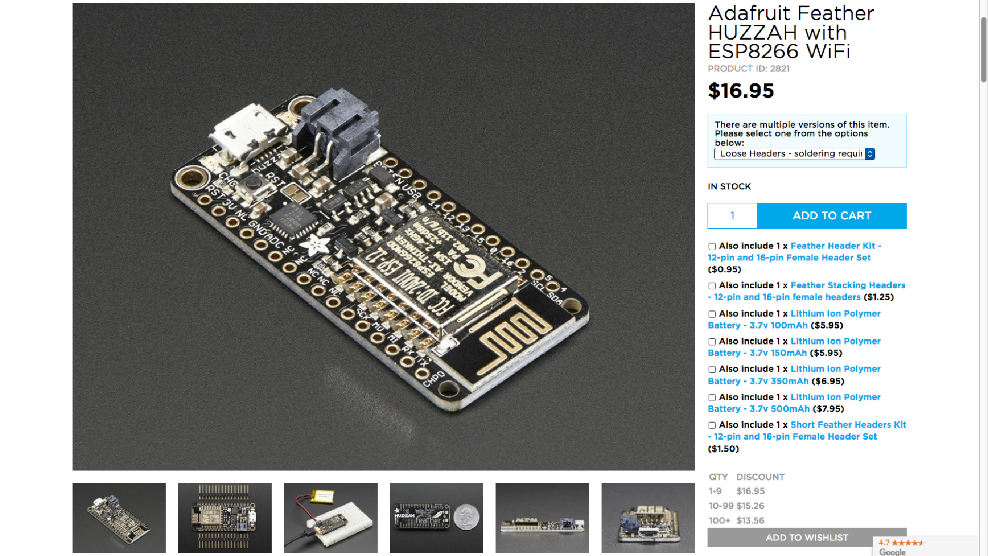
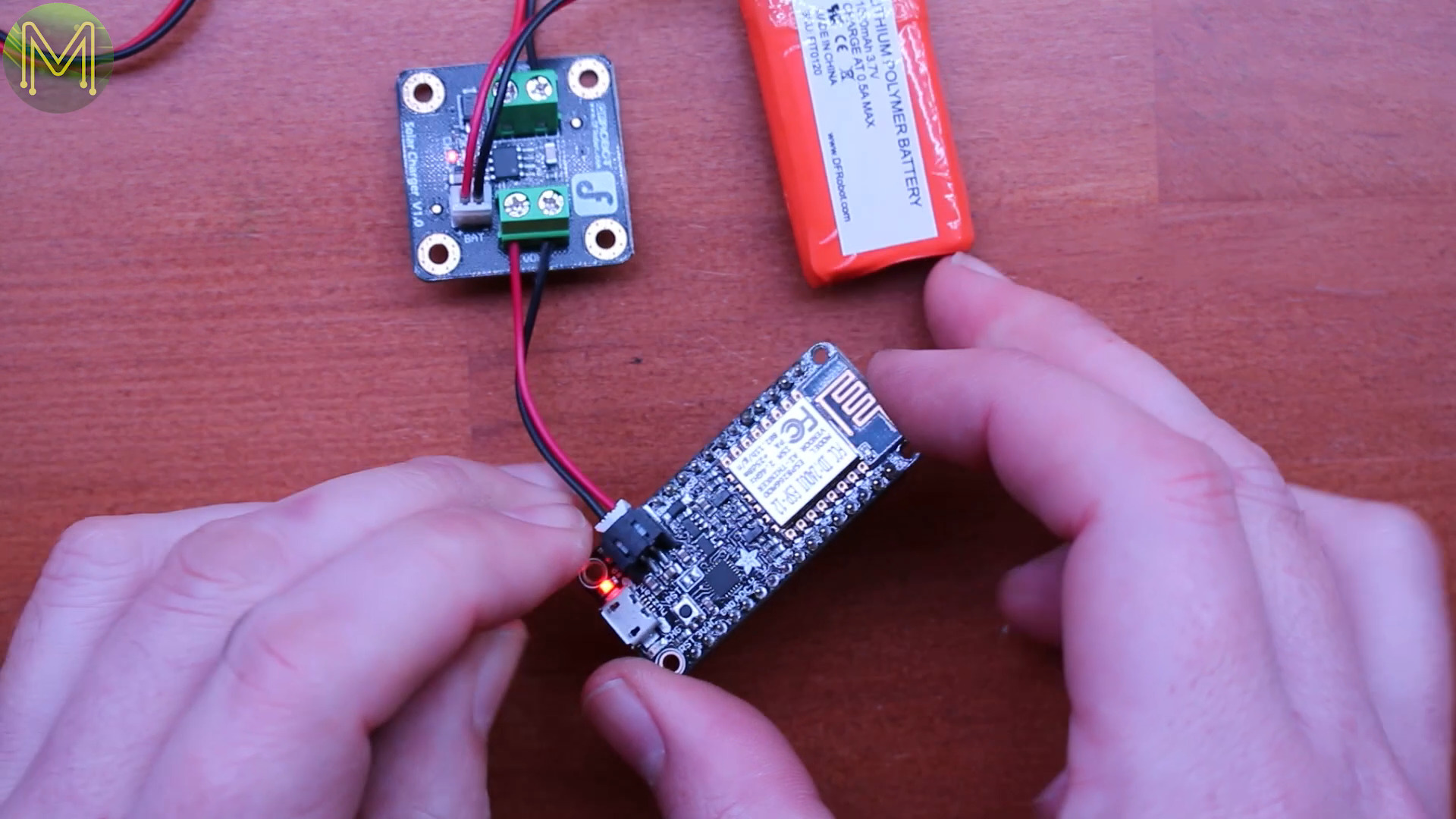
- ESP8266 Huzzah Feather
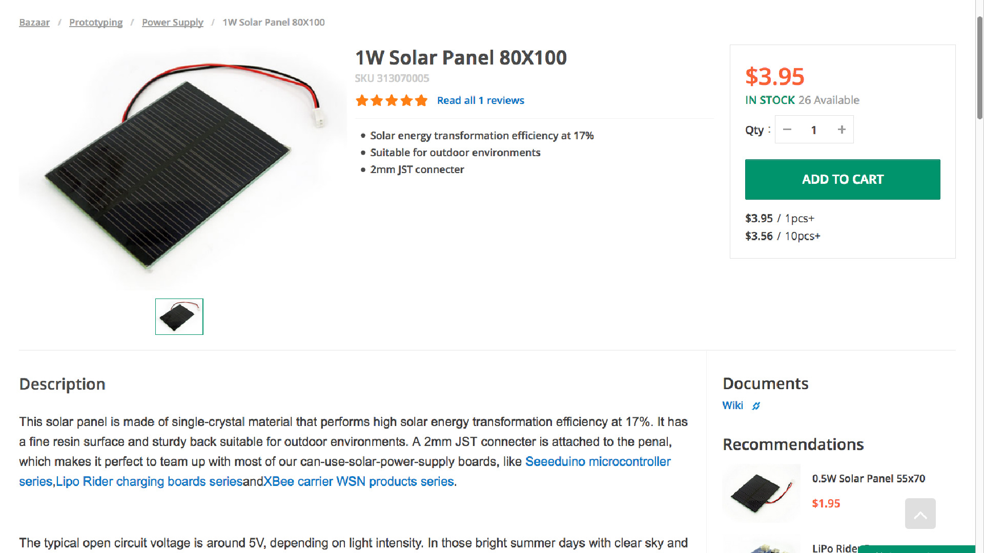
- 1W Solar Panel 80X100
- Solar LiPo Charger (3.7v)
- VeroBoard, or StripBoard
- Sharp GP2Y0D810Z0F Digital Distance Sensor
- Fast Vibration Sensor Switch
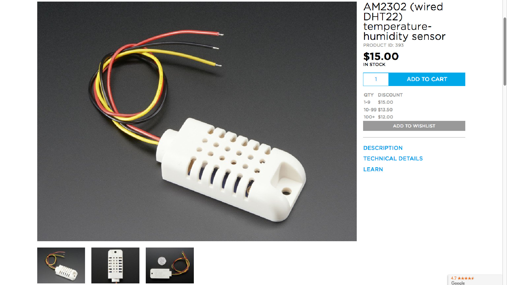
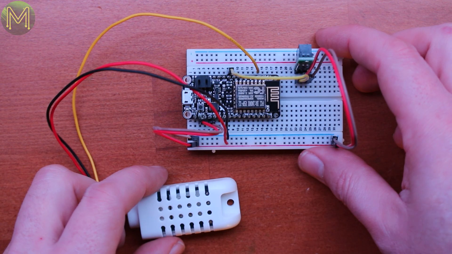
- AM2302 temperature-humidity sensor
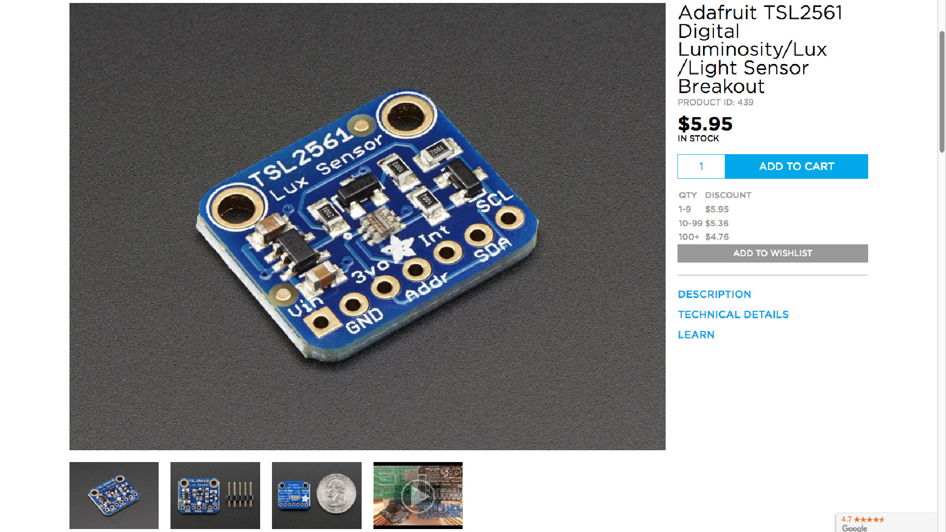
- Adafruit TSL2561 Lux Sensor
- 3.7V Polymer Lithium Ion Battery - 1000mAh On the software side I installed the TSL2561 and DHT22 library from AdaFruit, the Sharp distance sensor library, the PubSubClient MQTT library, and enabled support for the ESP8266 in my Arduino IDE.
Power to the people
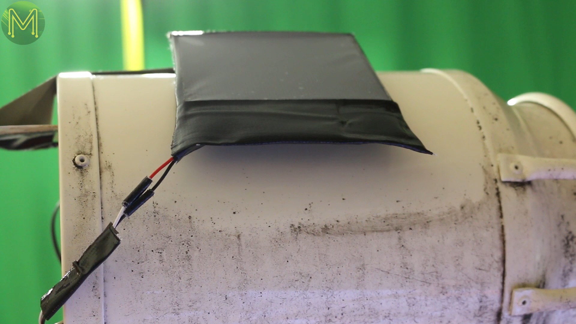
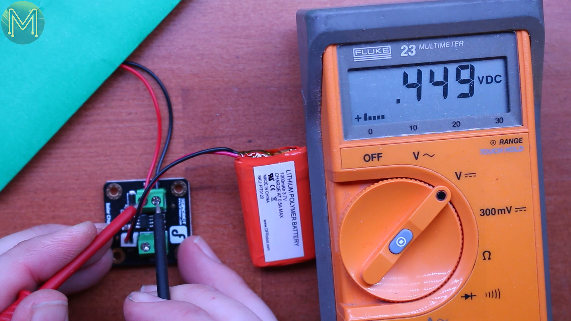
First of all I wanted to check out the power situation, so I cut off the header to the solar panel, stripped, tinned the wires, and then wired it up to the terminal block of the LiPo charger. With just my bright studio lights shining on the cell it was producing a steady 3.86v. Both the output terminal block and LiPo connector were pushing out 1.7v as these are tied together. Adding the LiPo of course saw 3.78v at the terminal block. Nice.Covering up the cell saw the voltage drop to under 1v and the output terminal maintaining the LiPo voltage. Good enough for my needs.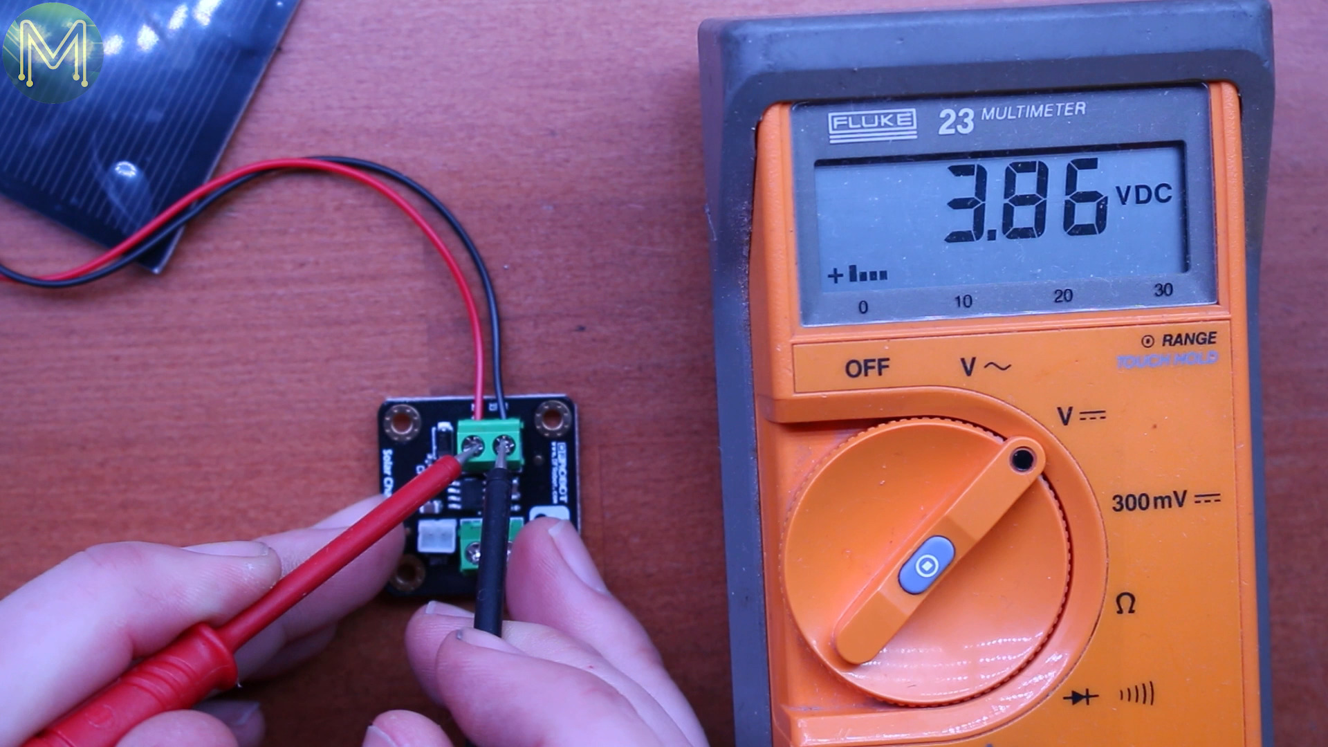
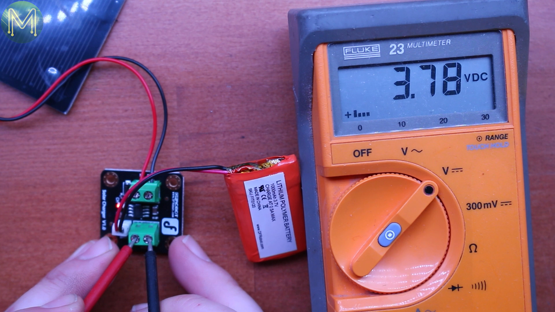
So, I prepared a JST header to be screwed into the output terminal block, which would provide uninterrupted power to my ESP8266. Nice.
The Five Senses
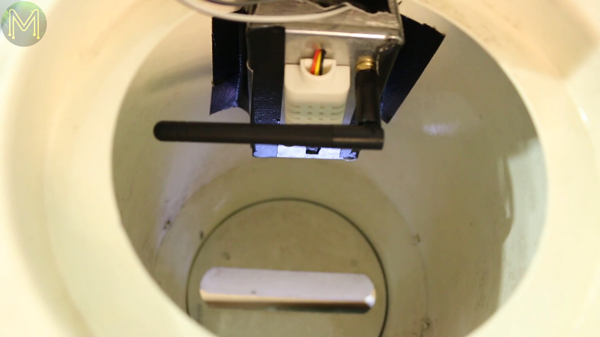
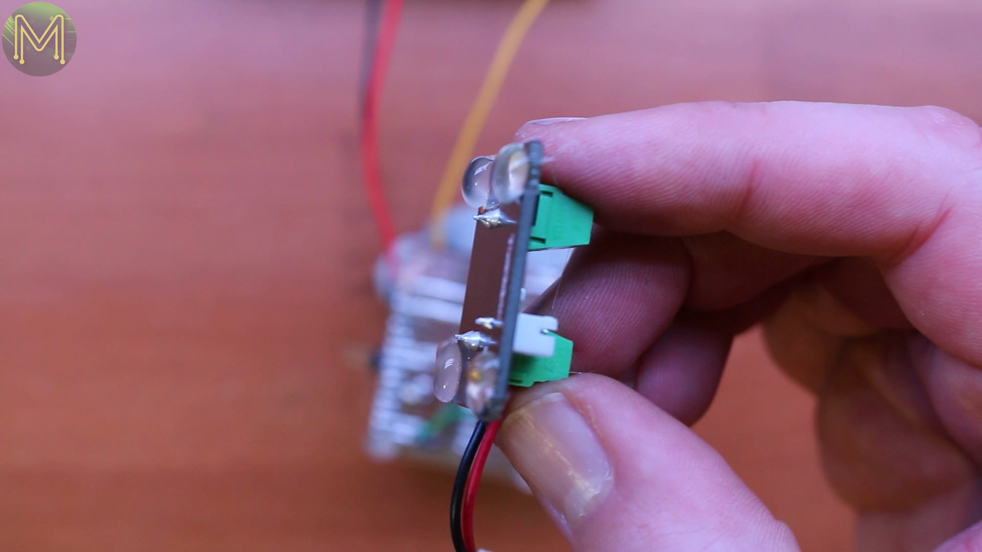
So, next I checked out the distance sensor.
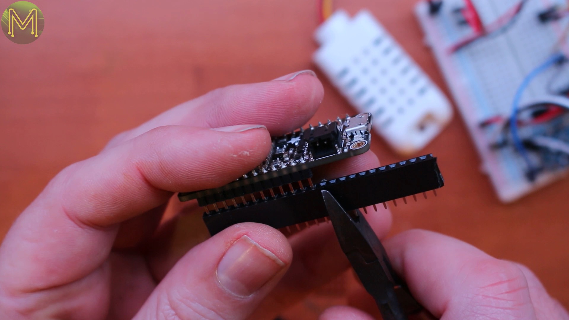
This unit is a simple break beam sensor that has on-board hysteresis so you get some fairly clean on or off states. None of the messy bouncing that would occur with micro-switches and a very reliable way of remotely detecting movement.After a fair bit of mucking around testing out sensors on my breadboard I moved over to something more permanent.I always like using these header blocks, because then I can reuse components from older projects instead of soldering everything permanently to the strip board.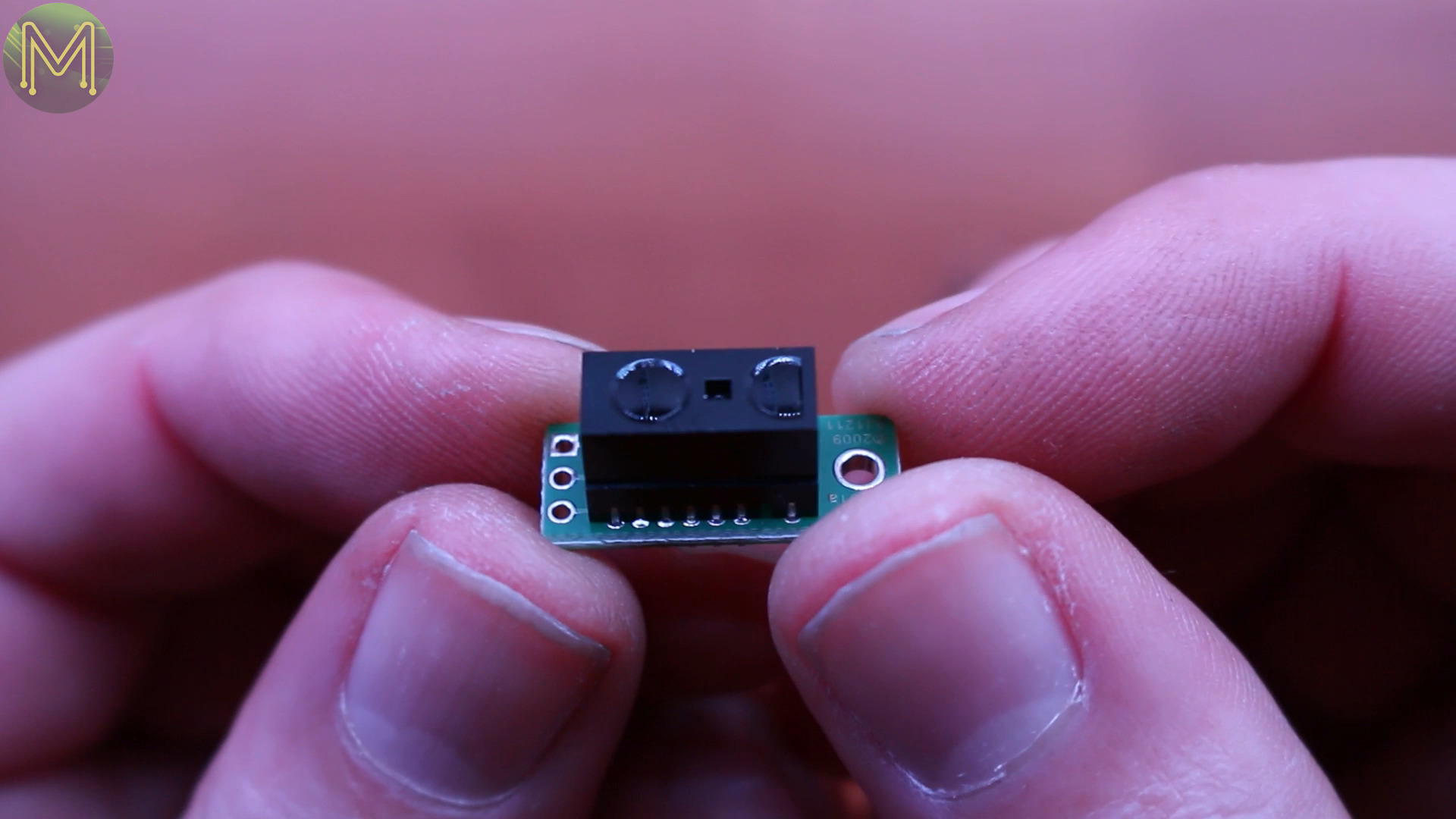
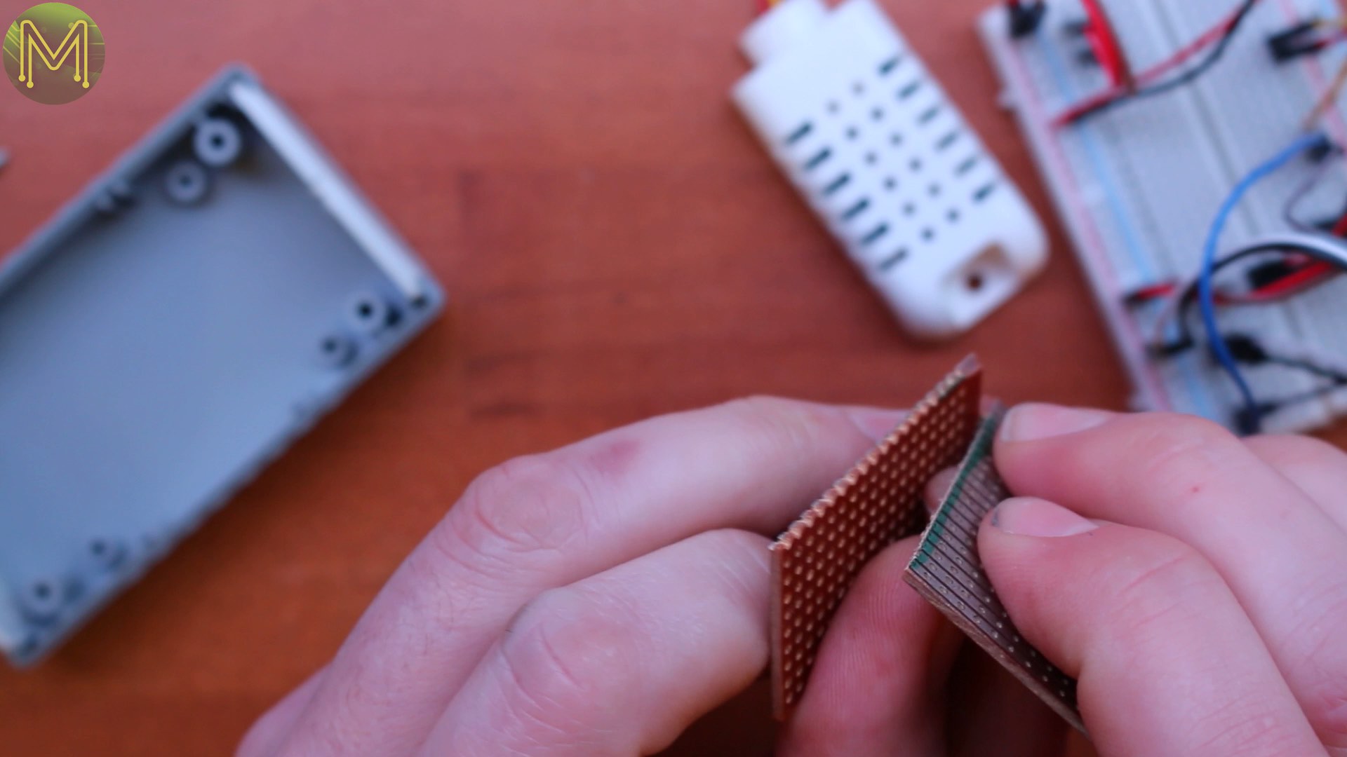
I found a decent case that I thought would fit everything in, so cut the strip board down to size. It’s pretty easy to do this, just mark out where to cut. You know the saying: measure twice, cut once.
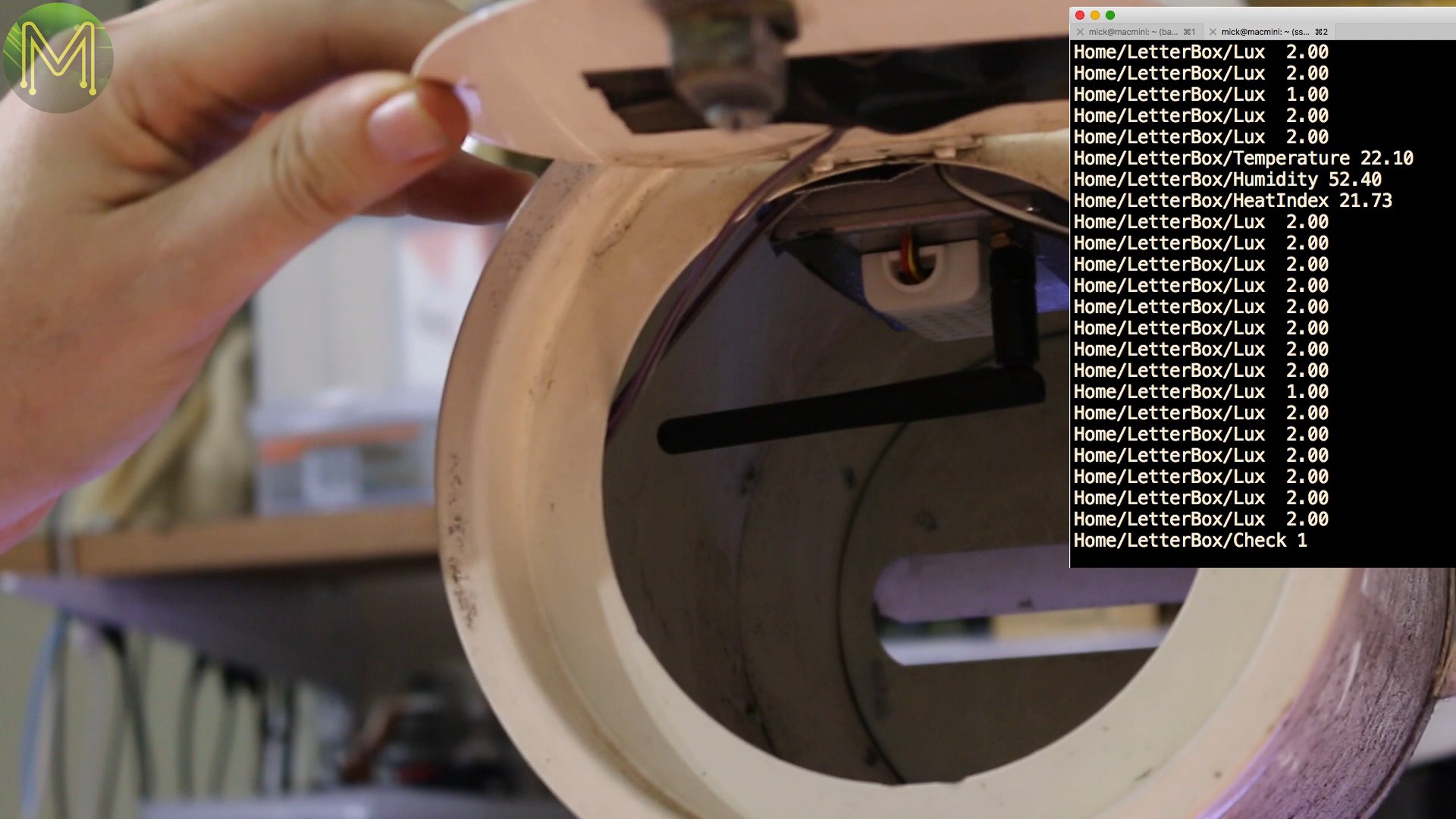
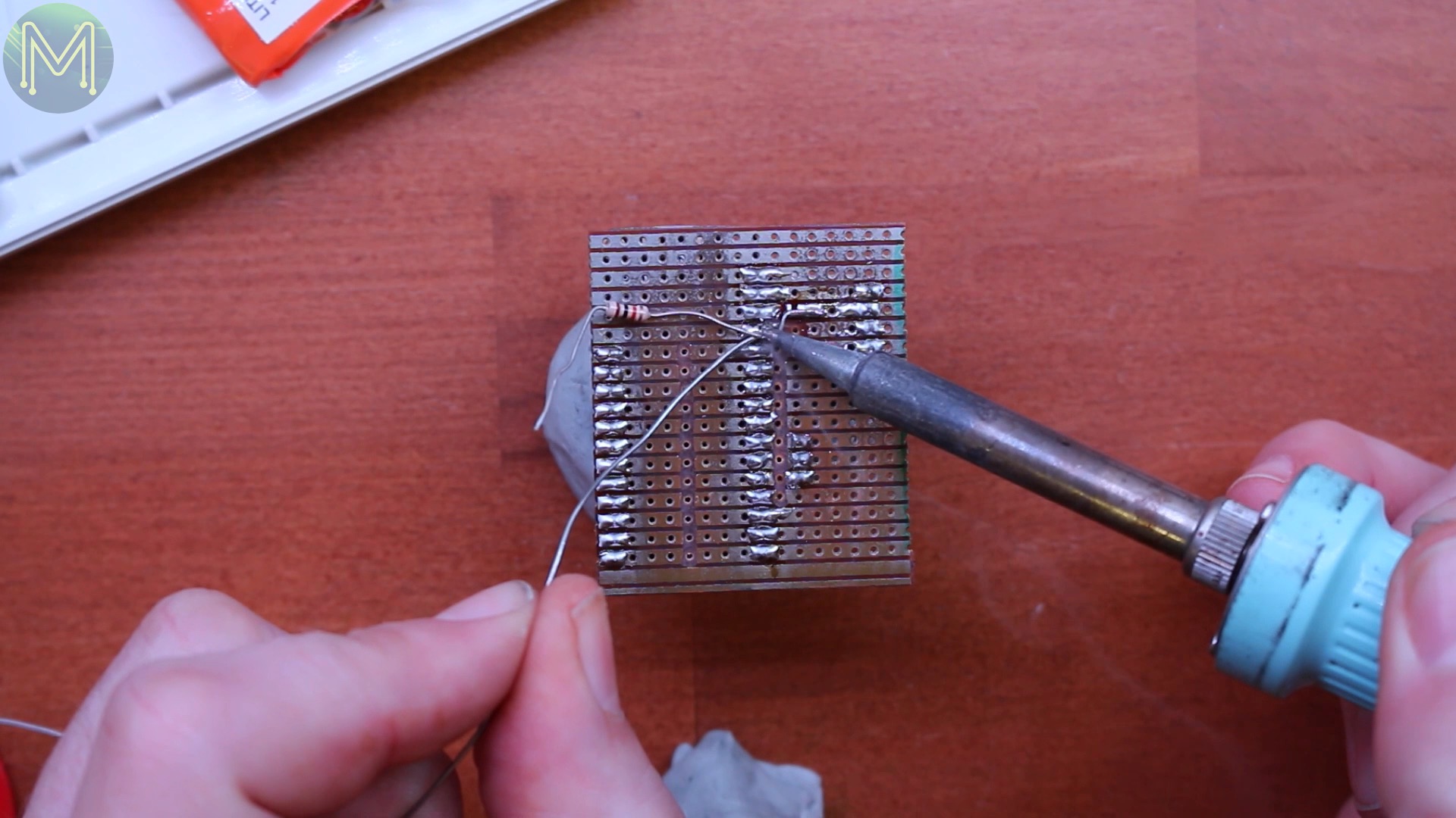
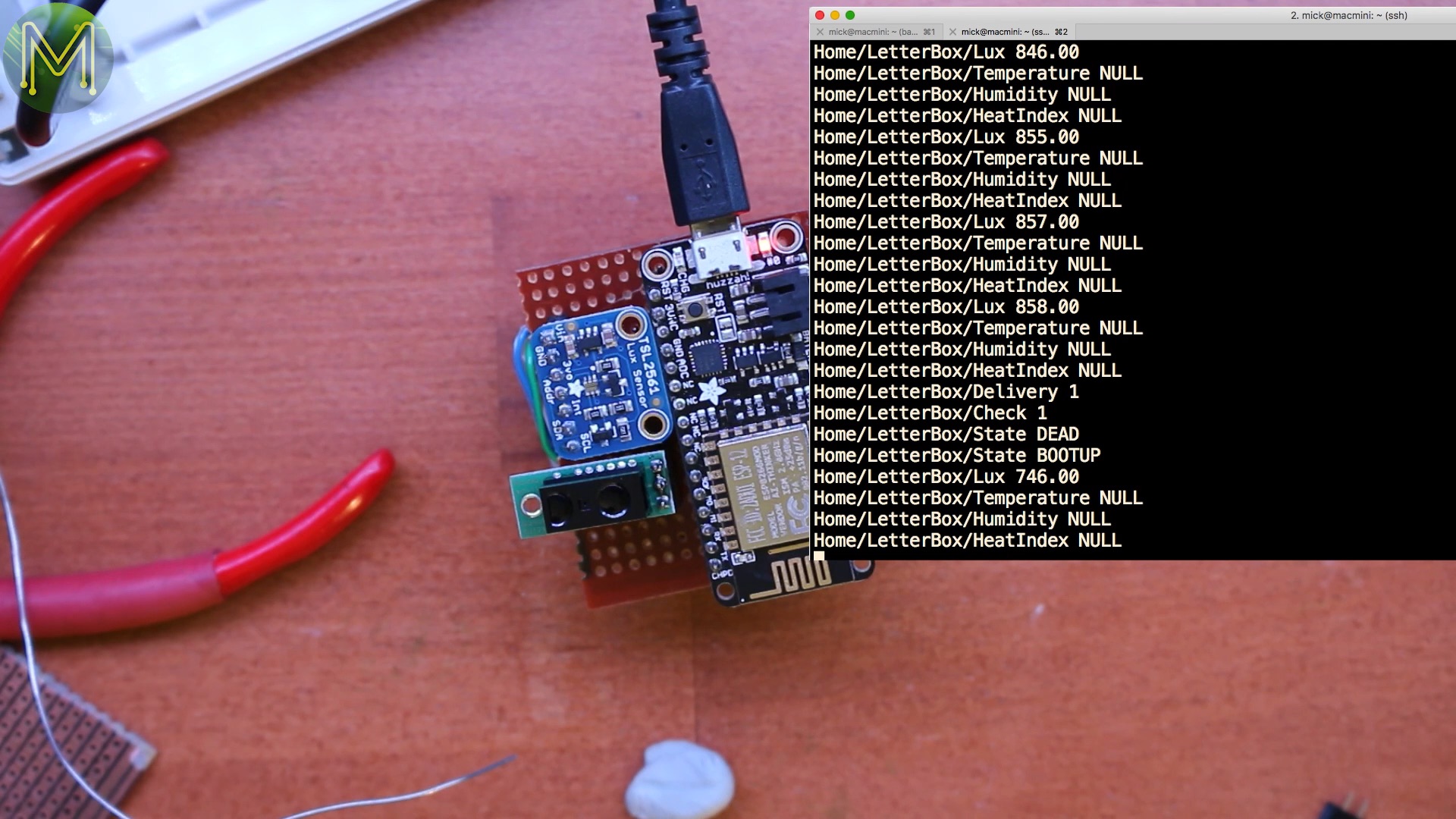
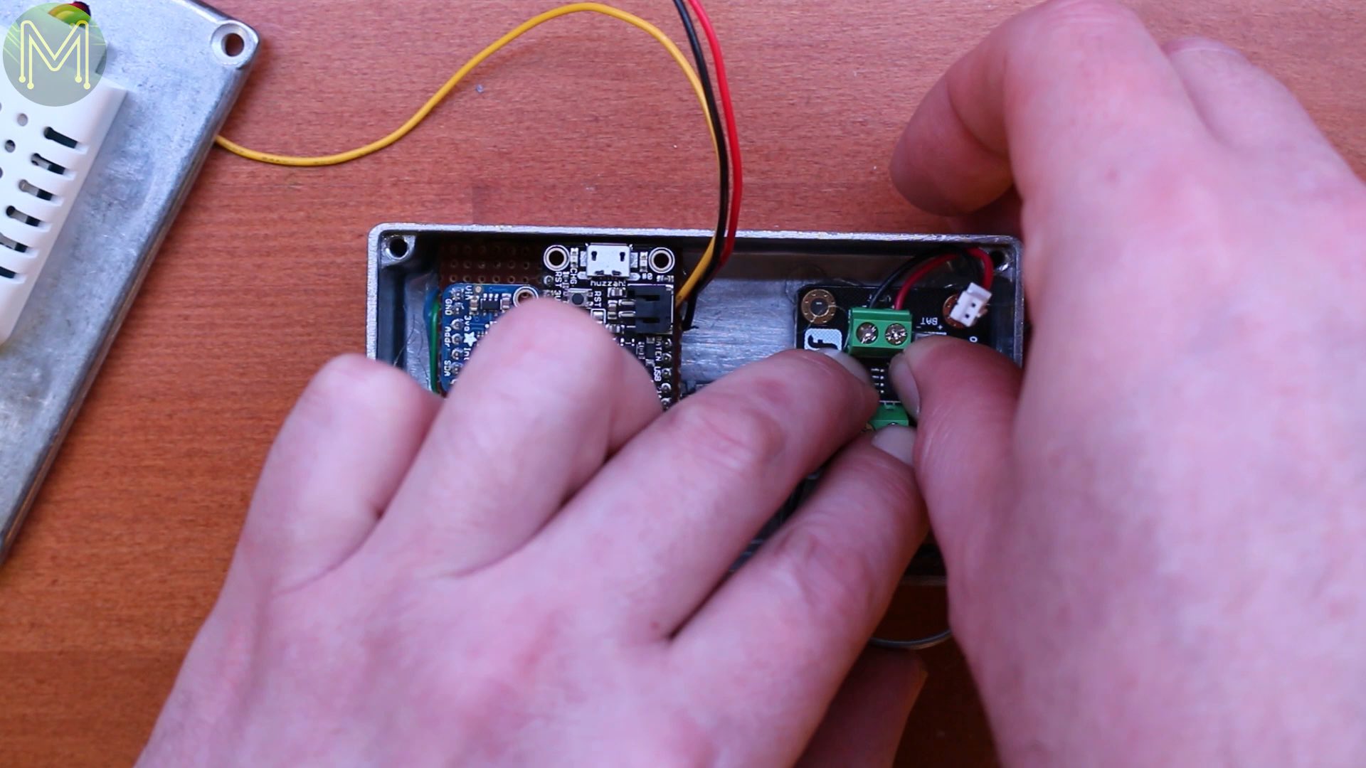
Score the board with a knife, and just snap it in two.Next to cut the tracks with a Dremmel that I don’t want connected, and start soldering up everything. Using the end wire of a resistor to bridge contacts works well, and you often tend to throw away the off-cuts. This is the ground wire for the Lux sensor, then there were the SDA & SCL I2C wires.The TSL2561 is a pretty accurate Lux sensor. A bit of overkill for my application, but I have 5 of them and I’ve been looking to use them somewhere. This is an I2C based sensor that consumes 15mA whilst in operation but can drop down to 15uA whilst powered down. Good for running off battery. Testing to make sure it worked. Yup, it was publishing Lux events to the MQTT Broker.Next on to the distance sensor. First power and then ground, then the signal wire from the sensor to GPIO pin 14 of the ESP8266. In my code I referred to this as the “deliver” pin. My ESP8266 would publish the number of times mail was delivered to a local MQTT broker which I had already setup. Both the sensor and MQTT network are pretty responsive. Just what I was looking for.Next on to the rear flap sensor, because I had some spare GPIOs and didn’t want to solder up any more wires, I used GPIO 13 as a lazy man’s ground for the sensor on GPIO 12, which had it’s own internal pull-up resistor.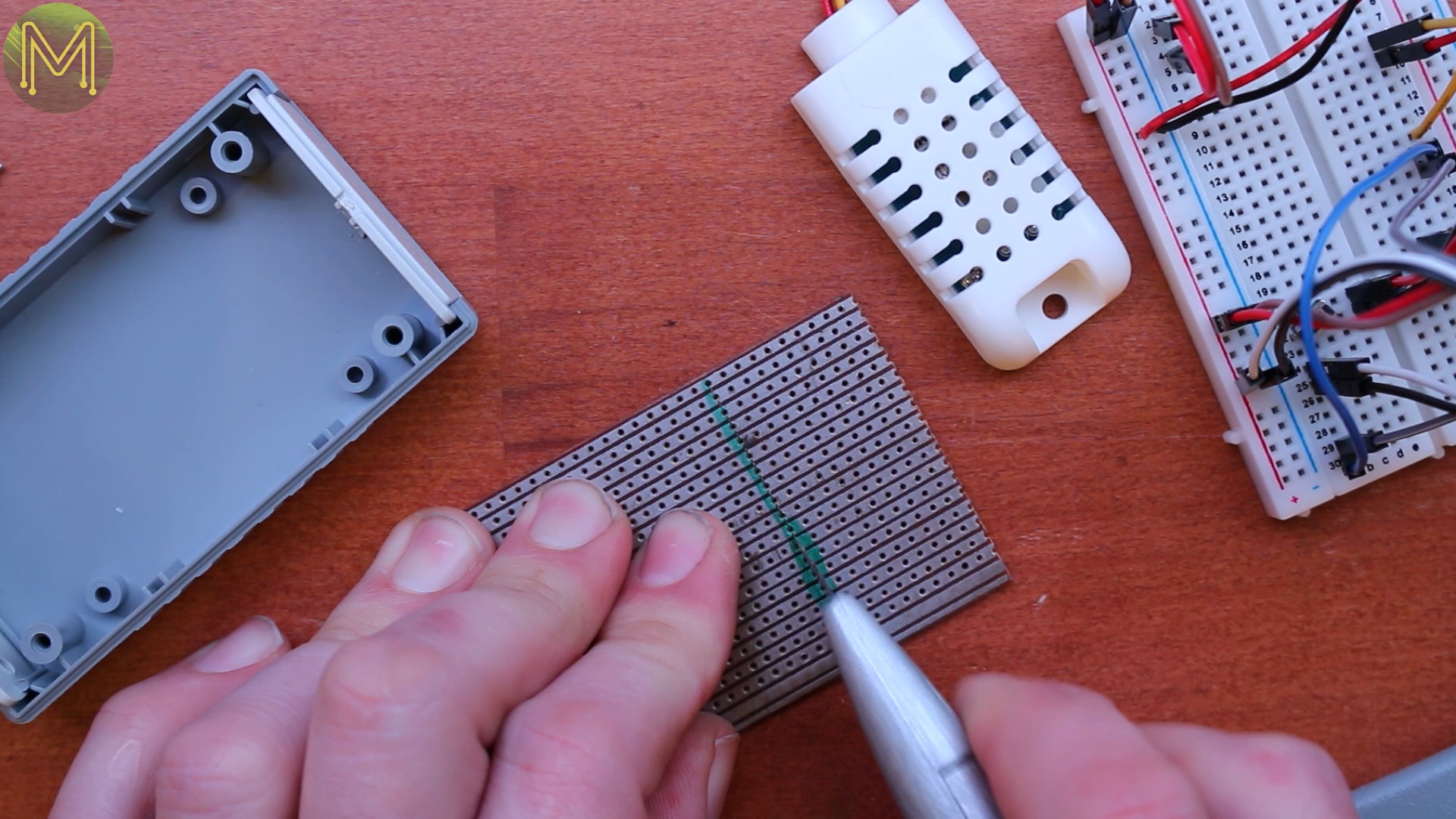

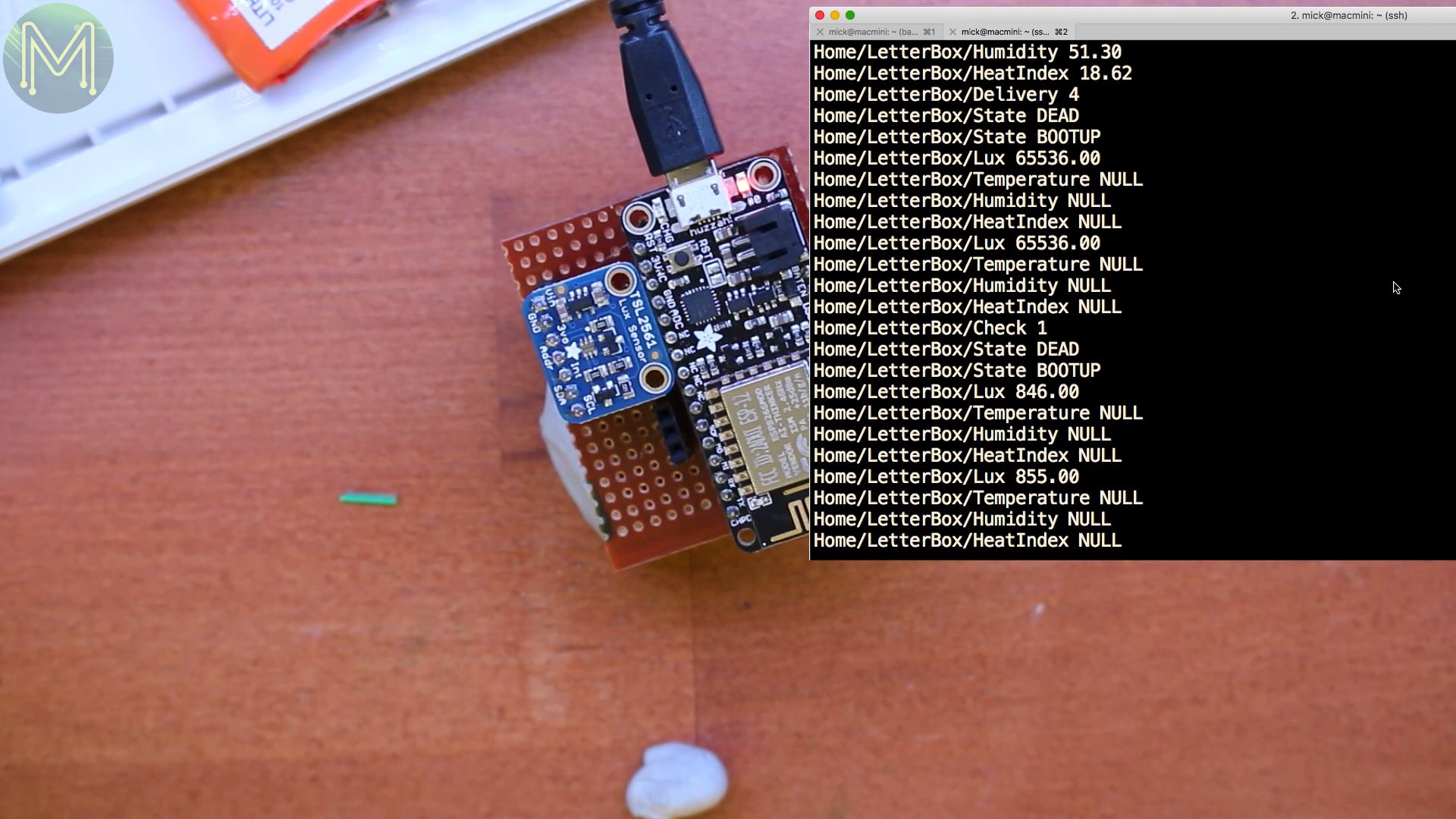

You will have noticed I always tend to test everything out at each stage of building to make sure it works. It avoids a lot of rework later. I’ve been down that path too many times.
Iron Maiden
On to cases!
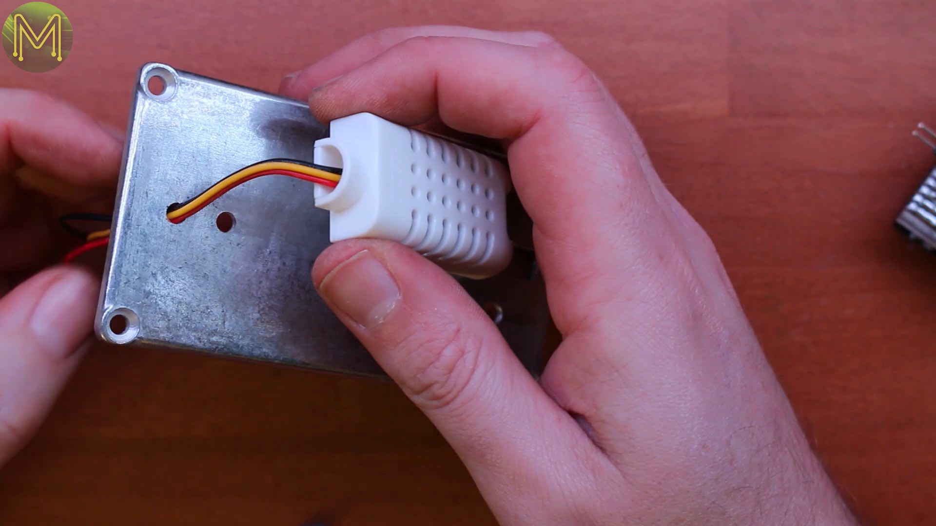
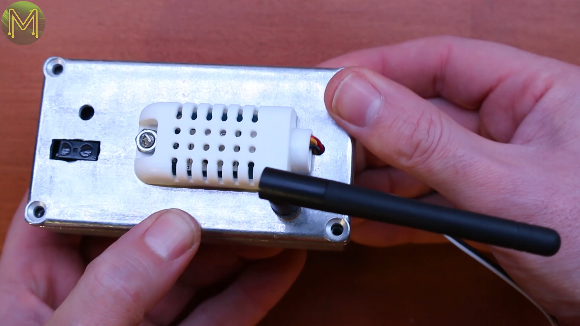
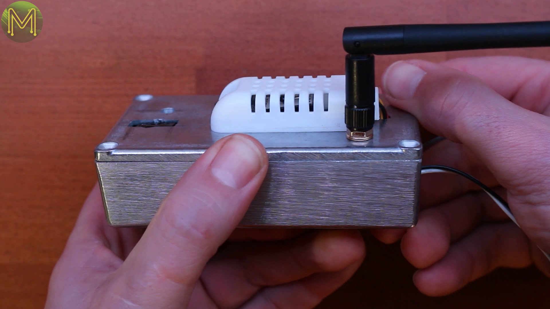
I finally found this rather excellent box aluminum box. So, next mark out where I need to drill holes in the lid. I need to be fairly accurate as I want to minimize mistakes.Then into the shed to drill out the holes, and back into the studio to square up the holes with a file.Next back into the shed again to drill holes out for the humidity sensor, to allow the cables to run inside the box and also allow me to attach it to the outside.To reduce the cost I didn’t bother with any stand-offs, but just used hot glue instead. This is a pretty simple method. Just apply a ball of hot glue to each corner and wait for it to harden. This acts as a raised point to avoid the board touching anything underneath. Then just before you mount it in the box apply another dab of hot glue and press firmly down.Now I had an issue. Since I was using the all metal box it acted as a Faraday Cage, which attenuated the WiFi signal considerably. So, I soldered up an external antenna. This is all fairly straightforward, but increases the range of your ESP8266 considerably. I should really have cut the old antenna track, but it didn’t seem to cause any issue.Then screwed the antenna jack to the body of the box. A bit of cable tidying up, inserting the battery, and there you have it!Pretty good, eh?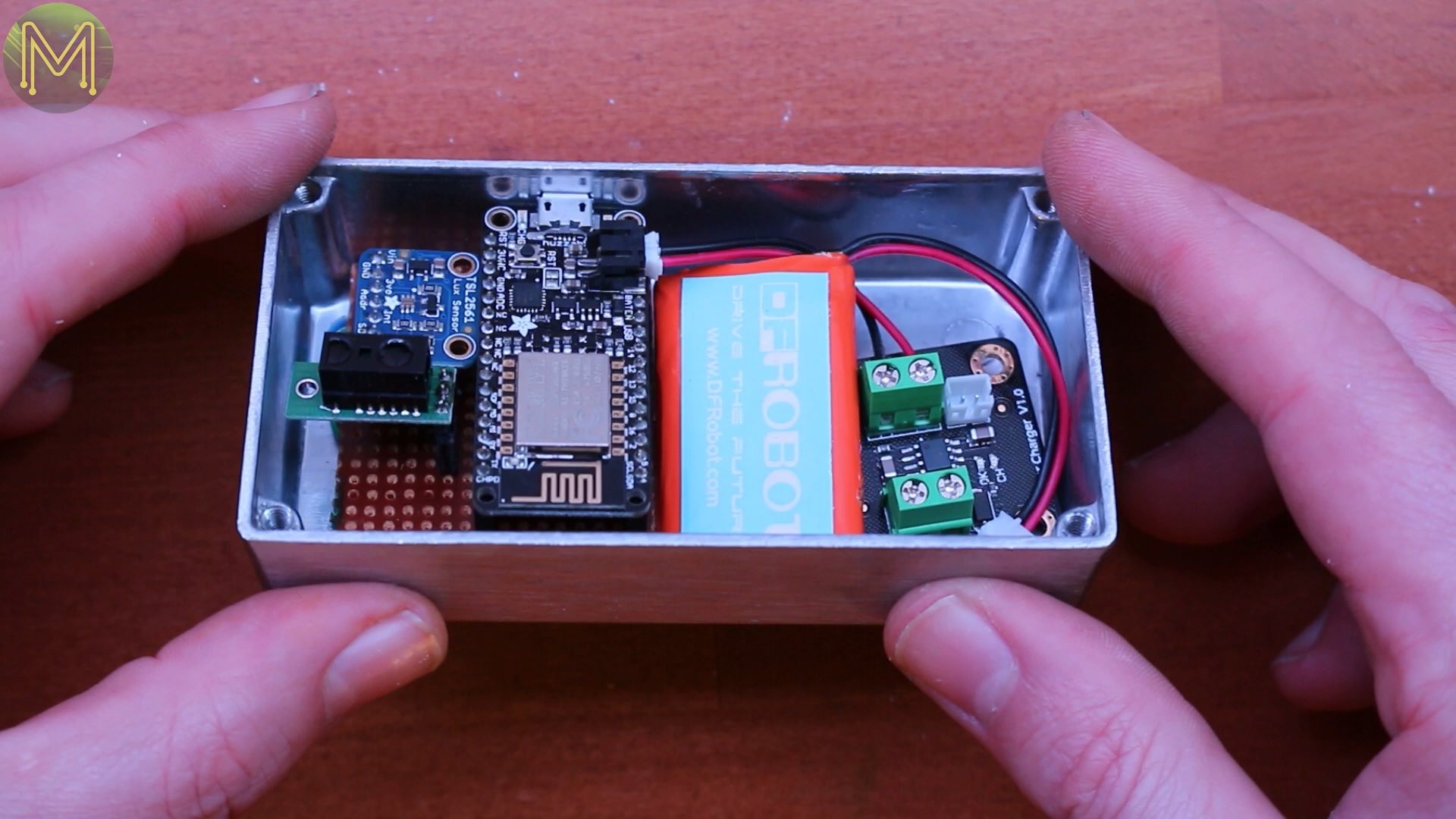


The code counts
So, a quick walk through of my code. You can pick up the full source code and schematics here. Note that I revisit this in my ESP battery optimization video. First of all include all the essential libraries. You can drop these libraries if you don’t need the Lux and temperature sensing.
#include <ESP8266WiFi.h>
#include <PubSubClient.h>
#include <stdio.h>
#include "DHT.h"
#include <Wire.h>
#include <Adafruit_Sensor.h>
#include <Adafruit_TSL2561_U.h>
Then come the important definitions:
For my local WiFi access point and MQTT server.
The macro that defines the MQTT Topic base string.
WiFiClient espClient; const char* ssid = “Somewhere”; const char* password = “Something”;
PubSubClient client(espClient); const char* mqtt_server = “my.mqtt.server”;
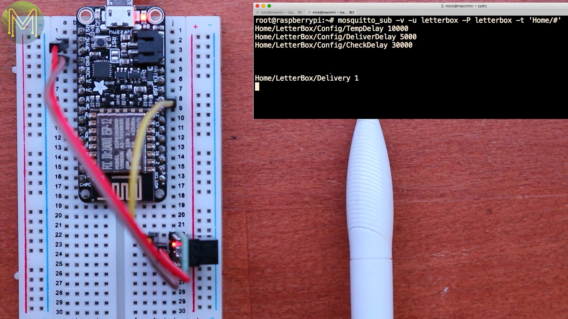
// Topic base for all comms from this device. #define TOPICBASE “Home/LetterBox/” The GPIO pins that are used for the DHT22 sensor, distance sensor, and rear flap movement sensor. The publishing wait time for the temperature and Lux sensors. The current values of those sensors and the current letter delivery count.
// Variables used for temperature & humidity sensing. #define TEMP_PIN 0 DHT dhtSensor(TEMP_PIN, DHT22); unsigned long confTempDelay = 10000; // Default temperature publish delay. unsigned long LastTempMillis = 0; // Stores the last millis() for determining update delay. float TempValue; float HumidValue; float HindexValue;
// Variables used for lux sensing. Adafruit_TSL2561_Unified LuxSensor = Adafruit_TSL2561_Unified(TSL2561_ADDR_FLOAT, 42); sensor_t LuxSensorInfo; unsigned long confLuxDelay = 10000; // Default temperature publish delay, (0 to disable). unsigned long LastLuxMillis = 0; // Stores the last millis() for determining update delay. float LuxValue;
// Variables used for when someone delivers mail to the mailbox. #define DELIVER_PIN 14 unsigned long confDeliverDelay = 5000; // Default time to wait to assume the next mail delivery event, (0 to disable). unsigned long DeliverLastMillis = 0; // Stores the last millis() when waiting for the next mail delivery event. boolean DeliverPubFlag = 0; // Used to keep client.publish out of int handlers. int DeliverCount = 0;
// Variables used for when someone checks the mailbox for mail. #define CHECK_PIN 12 #define LAZY_GND 13 // Instead of having to use additional wires. unsigned long confCheckDelay = 1000; // Default time to wait for mailbox check debounce, (0 to disable). unsigned long CheckLastMillis = 0; // Stores the last millis() when waiting for the mailbox check debounce. boolean CheckPubFlag = 0; // Used to keep client.publish out of int handlers. int CheckCount = 0; Then the setup of all the GPIOs. The DELIVER_PIN is setup as a falling interrupt and will execute DeliverFunc. As well as the CHECK_PIN calling CheckFunc. Then the setup of WiFi connectivity and sensors.
void setup() { //pinMode(BUILTIN_LED, OUTPUT); //digitalWrite(BUILTIN_LED, LOW);
  pinMode(DELIVER_PIN, INPUT);
  attachInterrupt(DELIVER_PIN, DeliverFunc, FALLING);

pinMode(LAZY_GND, OUTPUT);
digitalWrite(LAZY_GND, LOW);
  pinMode(CHECK_PIN, INPUT_PULLUP);
  attachInterrupt(CHECK_PIN, CheckFunc, FALLING);

  Serial.begin(115200);
  WiFiConnect();
  client.setServer(mqtt_server, 1883);
  client.setCallback(callback);

dhtSensor.begin();

if (!LuxSensor.begin())
{
  Publish((char *)"Lux", (char *)"DEAD");
}
else
{
  LuxSensor.enableAutoRange(true);
  LuxSensor.setIntegrationTime(TSL2561_INTEGRATIONTIME_402MS);
}
} Inside the loop function. The ESP will try to reconnect to MQTT if connectivity is lost. The next two code blocks are used to publish MQTT messages as you can’t do this from interrupts. I also reset the DeliverCount variable when someone opens the rear mailbox flap. Then I handle the regular publishing of temperature, humidity and sensor data.
void loop() { if (!client.connected()) { reconnect(); } client.loop();
// Publish - someone has put mail in the box.
  if (DeliverPubFlag)
  {
  PublishInt((char *)"Delivery", DeliverCount);
      DeliverPubFlag = 0;
  }

// Publish - someone has checked the box for mail.
if (CheckPubFlag)
  {
  PublishInt((char *)"Check", 1);
      CheckPubFlag = 0;
  }

if (confLuxDelay && (millis() - LastLuxMillis > confLuxDelay))
{
  LastLuxMillis = millis();

  sensors_event_t event;
  LuxSensor.getEvent(&event);

  if (event.light)
  {
    LuxValue = event.light;
    PublishFloat((char *)"Lux", LuxValue);
  }
  else
    Publish((char *)"Lux", (char *)"OL");
}

  if (confTempDelay && (millis() - LastTempMillis > confTempDelay))
  {
      LastTempMillis = millis();

      TempValue = dhtSensor.readTemperature();
  PublishFloat((char *)"Temperature", TempValue);

      HumidValue = dhtSensor.readHumidity();
  PublishFloat((char *)"Humidity", HumidValue);

      HindexValue = dhtSensor.computeHeatIndex(TempValue, HumidValue, false);
  PublishFloat((char *)"HeatIndex", HindexValue);
  }
} The next three functions are used to publish messages to the MQTT Broker. Either a plain string, converted integer or converted float.
void Publish(char *Topic, char *Message) { char TopicBase[80] = TOPICBASE;
strcat(TopicBase, Topic);
client.publish(TopicBase, Message);
}
void PublishInt(char *Topic, int Value) { char TopicBase[80] = TOPICBASE; char Message[10] = “NULL”;
if (!isnan(Value))
  itoa(Value, Message, 10);

strcat(TopicBase, Topic);
client.publish(TopicBase, Message);
}
void PublishFloat(char *Topic, float Value) { char TopicBase[80] = TOPICBASE; char Message[10] = “NULL”;
if (!isnan(Value))
  dtostrf(Value, 5, 2, Message);

strcat(TopicBase, Topic);
client.publish(TopicBase, Message);
} The next function handles connectivity to the MQTT Broker and once connected will subscribe to several important Topics. I use this topic to automatically update the ESPs important variables defined above.
void reconnect() { // Loop until we’re reconnected while (!client.connected()) { // Attempt to connect if (client.connect(“LetterBox”, “letterbox”, “letterbox”, (char *)TOPICBASE “State”, 1, 0, “DEAD”)) { // Once connected, publish an announcement… Publish((char *)“State”, (char *)“BOOTUP”); // Subscribe to enable bi-directional comms. client.subscribe(TOPICBASE “Config/#"); // Allow bootup config fetching using MQTT persist flag! client.subscribe(TOPICBASE “Put/#"); // Send commands to this device, use Home/LetterBox/Get/# for responses. } else delay(5000); } } All I have to do is run these commands from any client to change values on the ESP. Note that I set the message to be retained. This means every time the ESP subscribes to the Config Topic, the MQTT Broker will publish these messages and the ESP will update the variables. Nice!
mosquitto_pub -q 2 -i LetterBox -u letterbox -P letterbox -r -t Home/LetterBox/Config/CheckDelay -m 5000 mosquitto_pub -q 2 -i LetterBox -u letterbox -P letterbox -r -t Home/LetterBox/Config/DeliverDelay -m 2000 mosquitto_pub -q 2 -i LetterBox -u letterbox -P letterbox -r -t Home/LetterBox/Config/TempDelay -m 60000 mosquitto_pub -q 2 -i LetterBox -u letterbox -P letterbox -r -t Home/LetterBox/Config/LuxDelay -m 60000 This is actually a really great feature of MQTT. Why not publish compiled code to a topic and have the ESP perform OTA programming on itself?
The next important functions are the interrupts I mentioned earlier. This one will fire when someone puts mail in the front of the box and this one when someone retrieves mail at the back. Note that I temporarily disable interrupts while this function executes. I don’t want any bizarre race conditions occurring.
void DeliverFunc()
{
    noInterrupts();

    if ((millis() - DeliverLastMillis) > confDeliverDelay)
    {
        DeliverPubFlag = 1;
        DeliverCount++;
    }
    DeliverLastMillis = millis();

    interrupts();
}


void CheckFunc()
{
    noInterrupts();

    if ((millis() - CheckLastMillis) > confCheckDelay)
    {
        CheckPubFlag = 1;
        DeliverCount = 0;
        CheckCount = 0;
    }
    // CheckCount++;
    CheckLastMillis = millis();

    interrupts();
}
The callback function will be called by the PubSubClient library and will provide the topic and message payload.
First, there seems to be a small bug in this library which doesn’t place a zero terminating byte at the end of the payload string every time. So, I had to add this quick hack in.
Second, I check for any published message that contains the Config Topic, and then update the important variables.
void callback(char* topic, byte* payload, unsigned int length)
{
    payload[length] = 0;    // Hack to be able to use this as a char string.

    if (strstr(topic, TOPICBASE "Config/"))
    {
        if (strstr(topic, "TempDelay"))
                confTempDelay = atoi((const char *)payload);

        else if (strstr(topic, "DeliverDelay"))
            confDeliverDelay = atoi((const char *)payload);

        else if (strstr(topic, "CheckDelay"))
            confCheckDelay = atoi((const char *)payload);

        else if (strstr(topic, "LuxDelay"))
            confLuxDelay = atoi((const char *)payload);
    }
}
That’s about it for the code walk-through.
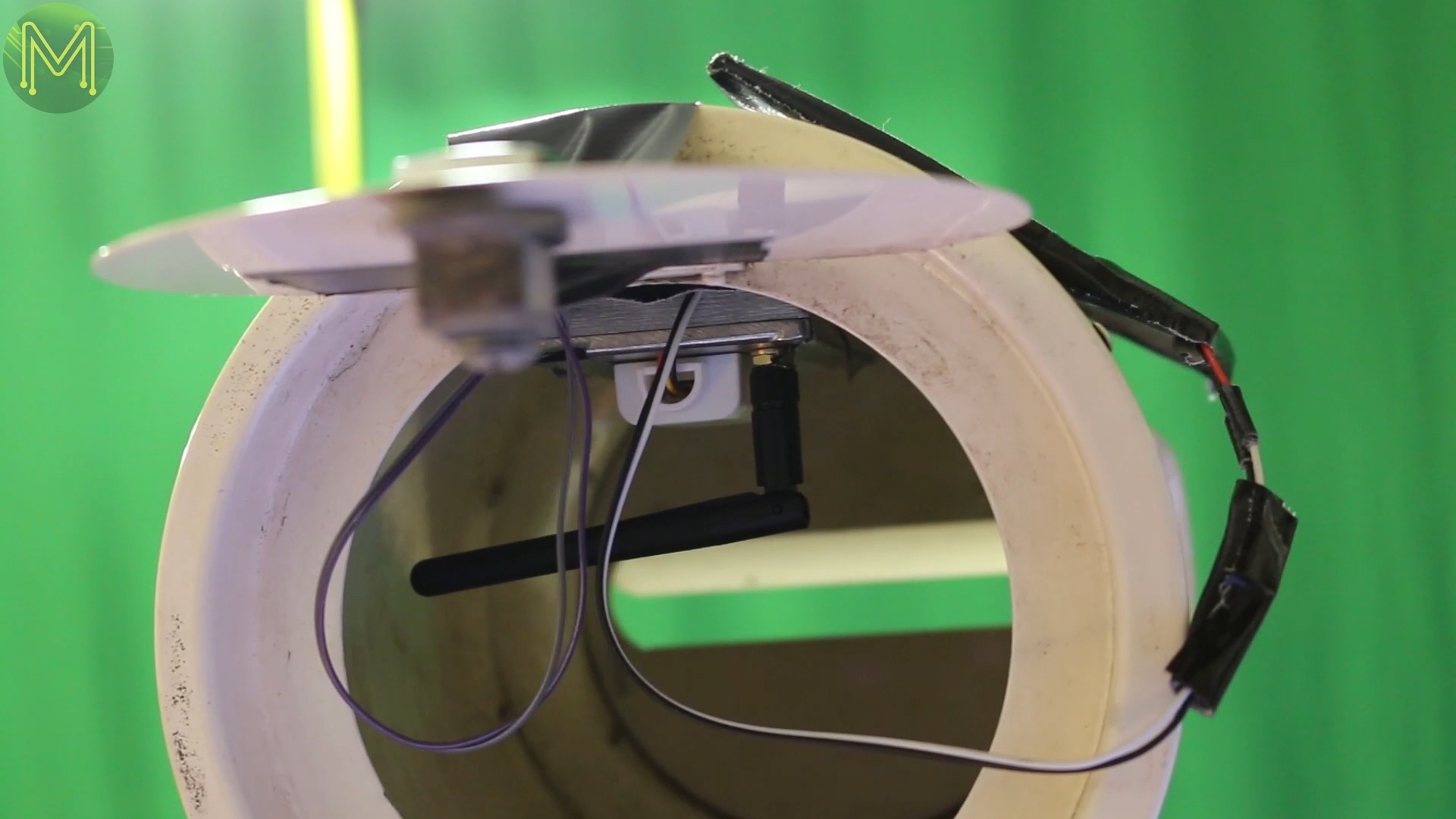
The prototype
So, here’s the prototype. In following videos I’ll be looking at push alerts from MQTT servers, ESP8266 power optimization and building a better, more permanent enclosure.